1–38 Chapter 1: Cyclone IV Transceivers Architecture
Transceiver Clocking Architecture
Cyclone IV Device Handbook, February 2015 Altera Corporation
Volume 2
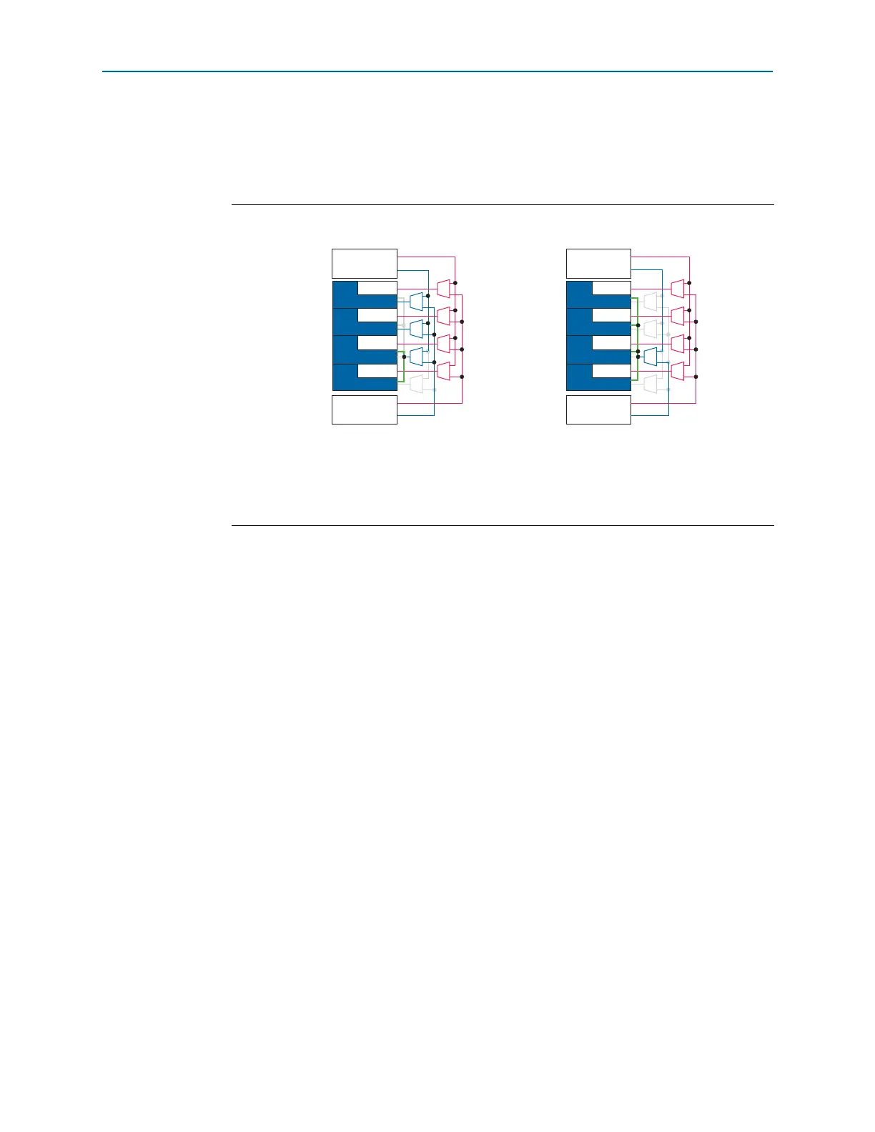
Figure 1–36 and Figure 1–37 show the independent high-speed clock and bonded
low-speed clock distributions for transceivers in F324 and smaller packages, and in
F484 and larger packages in bonded (×2 and ×4) channel configuration.
Figure 1–36. Clock Distribution in Bonded (×2 and ×4) Channel Configuration for Transceivers in
F324 and Smaller Packages.
Notes to Figure 1–36:
(1) Transceiver channels 2 and 3 are not available for devices in F169 and smaller packages.
(2) High-speed clock.
(3) Low-speed clock.
(4) Bonded common low-speed clock path.
Transceiver
Block
GXBL0
2 Bonded Channel Configuration
+
MPLL_2
TX PMA
TX PMA
TX PMA
TX PMA
Ch3
(1)
MPLL_1
Ch2
(1)
Ch1
Ch0
(3)
(4) (4)
(2)
Transceiver
Block
GXBL0
4 Bonded Channel Configuration
+
MPLL_2
TX PMA
TX PMA
TX PMA
TX PMA
Ch3
(1)
MPLL_1
Ch2
(1)
Ch1
Ch0
(3)
(2)