1–60 Chapter 1: Cyclone IV Transceivers Architecture
Transceiver Functional Modes
Cyclone IV Device Handbook, February 2015 Altera Corporation
Volume 2
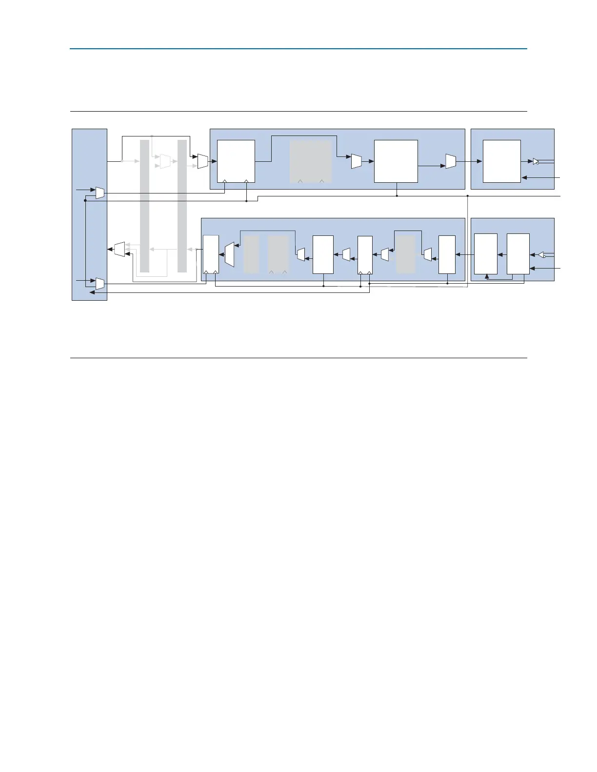
Figure 1–55 shows the transceiver channel datapath and clocking when configured in
GIGE mode.
Figure 1–55. Transceiver Channel Datapath and Clocking when Configured in GIGE Mode
Notes to Figure 1–55:
(1) Low-speed recovered clock.
(2) High-speed recovered clock.
(3) Optional
rx_recovclkout
port from CDR low-speed recovered clock is available for applications such as Synchronous Ethernet.
(1)
Byte Serializer
8B/10B Encoder
Transmitter Channel PCS Transmitter Channel PMA
Serializer
PCIe Hard IP
FPGA
Fabric
PIPE Interface
Tx Phase
Comp
FIFO
tx_datain
tx_dataout
wr_clk rd_clk
wr_clk rd_clk
high-speed
clock
low-speed clock
tx_coreclk
tx_clkout
rx_coreclk
Receiver Channel PCS Receiver Channel PMA
rx_dataout
(3)
rx_datain
Deserial-
izer
CDR
Byte
De-
serializer
Byte
Order-
ing
Deskew
FIFO
8B/10B
Decoder
Rate
Match
FIFO
CDR clock
(2)
Word
Aligner
Rx
Phase
Comp
FIFO
rx_recovclkout