S820E UG PN: 10580-00343 Rev. H 3-35
Cable and Antenna Measurements 3-7 Measurement Setup
Limit Line Segments
3. For segmented limit lines, press Edit Segments to display the Segments
menu. A table displays active limit lines and segments.
4. Tap on a limit line segment and then choose to Add, Edit, or Delete the
segment. For editing purposes, consider a single, full-span limit line as
a single segment. Press the Close submenu key or the escape (ESC) key
to close the Edit Segments menu and return to the Limit menu.
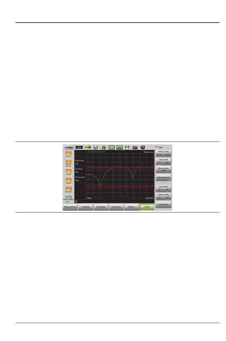
Upper limit lines and segments are labeled with a “U”, and Lower limit lines
and segments are labeled with an “L”. Limit lines are displayed in green so
long as the limits are not reached or exceeded. When a limit is exceeded
(upper or lower), the limit line or segment turns red (Figure 3-17). Any
portion of the measurement trace touching or exceeding a limit also turns
red, while portions of the trace within limits remain in the default yellow
color. When Segmented Limits are used, the trace color does not change when
a limit is exceeded.
Figure 3-17. Limit Lines and Trace Showing Fail Colors