10. Maintenance
Image 10-58
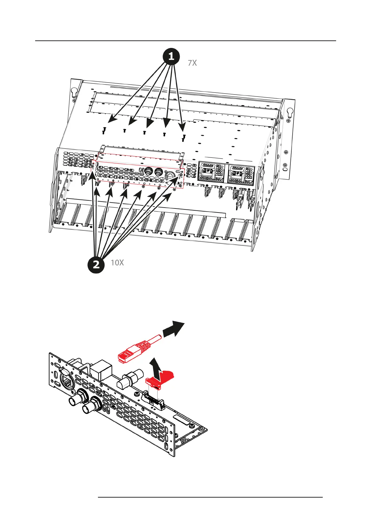
3. Gently pull the Genlock a ssem bly away from the un
it . Don’t pull the assembly too far back because there are s till 2 cables
attached.
Note: At this po int there are still 2 cables c onnecting the Genlock Assem bly to the unit.
4. Unlatch the VFD ribbon cable from the connector a nd pull it up and away from the Genlock board.
Note: This cable connects the Genloc k board to the System-Power board.
Image 10-59
5. Unlatch the Ethernet cable from the connector and pull back and away from the Genlock bo ard.
Note: This cable connects the Genloc k board to the System-Power board.
R5905948 E2 12/12/2014
251