3. General
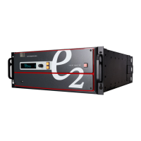
a) Measure and install the two supplied m ounting brackets on your rear rack rails.
Image 3-2
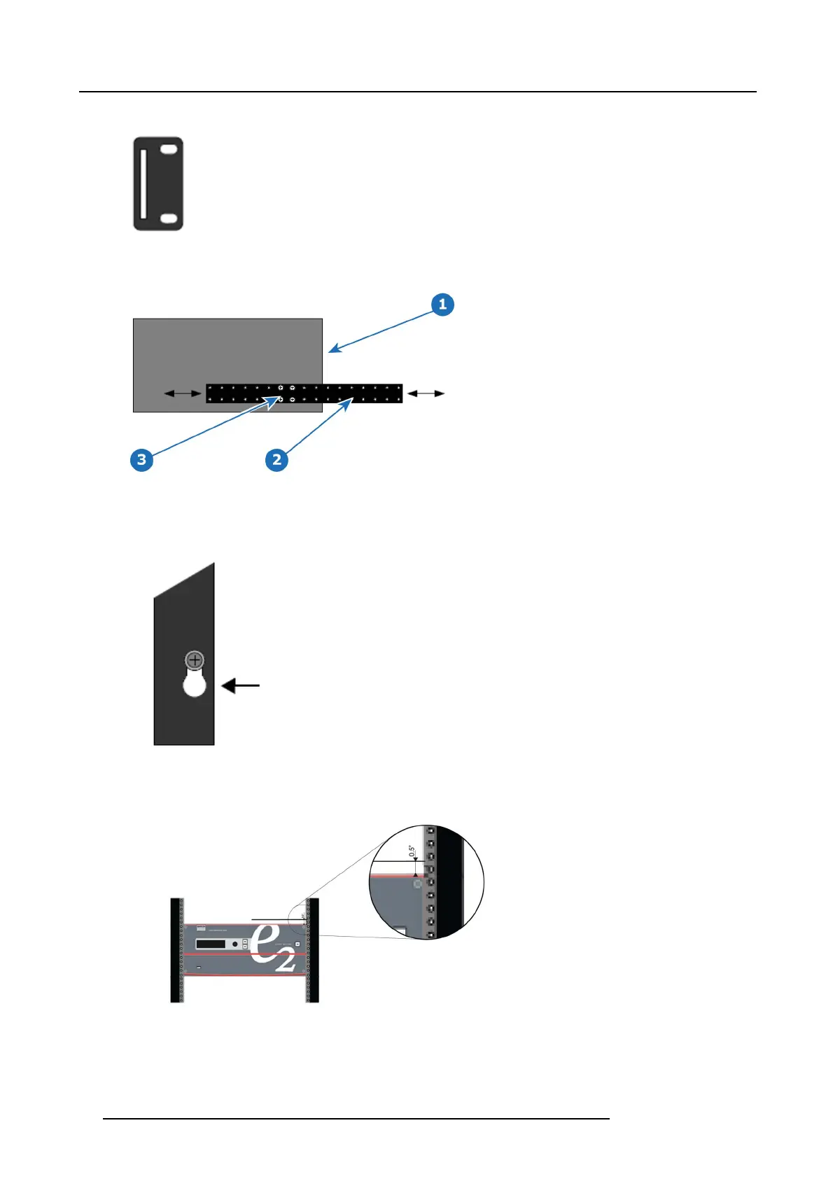
b) Measure the distance between the front and rear rack rails. Remove the four mounting screws that secu
re ea ch side rail t o
the E2, and then adjust the spacing of each side rail as necessary.
Image 3-3
1 Chassis rear
2Siderail
3 M ounting screws
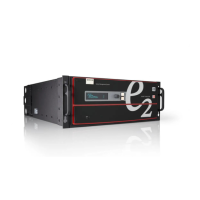
c) Re-install the mounting screws. When properly adjusted, the end of each side rail will protrude through the slot in the rear
mounting bracket, once the chassis is rack mounted.
Image 3-4
To take advantage of this feature, ensure that there is at least 1/2” of clearance above the chassis.
Image 3-5
2. For the E2’s two keyhole slots, m easure and install two rack screws in your equipment rack’s front rails. A llow each screw to
protrude approximately 3/4” from the surface o f the rails.
3. Lift the chassis, and while supporting it, slide the side rails through the slots in the rear mounting brackets.
26
R5905948 E2 12/12/2014