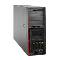
RX2520 M4
Upgrade and Maintenance Manual 329
– (1) Front panel cable to connector "FRONTPANEL1".
– (2) Front USB cable to connector "USB3.0 FRONT".
Ê If applicable, connect the cables of the ODD:
– ODD power cable to connector X17 on the backplane, see section
"Connecting a 3.5-inch HDD backplane" on page 173.
– ODD SATA cable to connector SATA ODD on the system board.
Ê If applicable, install the expansion card in slot 4, see section "Installing
expansion cards" on page 207.
I For the cable plan, see chapter "Appendix B" on page 411.
Ê Carefully pull the front panel module into its bay and regard that the locking
mechanism snaps in (see circle).
V CAUTION!
Ensure that none of the cables are strained or damaged.
13.3.1.6 Concluding steps
Ê "Installing the fan holder" on page 64
Ê "Installing the air duct" on page 62
Ê "Reassembling" on page 55
Ê "Connecting the power cord" on page 59
Ê "Switching on the server" on page 60
Ê "Verifying system information backup/restore" on page 74
Ê Store your server’s system information on the Chassis ID EPROM
integrated into the front panel board. For more information on how to obtain
and use the ChassisId_Prom Tool, see section "Using the Chassis ID Prom
Tool" on page 93.
Ê "Resuming BitLocker functionality" on page 89
 Loading...
