4-70 Service Manual
7510
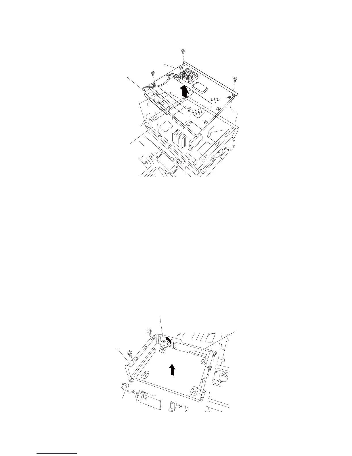
8. Remove the RIP card cooling fan cover assembly (A).
Controller box assembly removal
1. Remove the rear cover assembly. See “Rear cover assembly removal” on page 4-5.
2. Remove the right cover assembly. See “Right cover assembly removal” on page 4-4
3. Remove the top cover assembly. See “Top cover assembly removal” on page 4-4.
4. Remove the RIP card assembly. See “RIP card assembly removal” on page 4-73.
5. Remove the controller box top cover assembly. See “RIP card cooling fan cover assembly removal” on
page 4-69.
6. Remove the switch (main power). See “Switch (main power) removal” on page 4-71.
7. Loosen the screw securing the ground wire (A).
8. Remove the ground wire (A).
9. Disconnect the connector (B), and rotate it 90°.
10. Remove the connector (B).
11. Remove the four screws securing the controller box assembly (C) to the machine.
Note: When lifting the controller box assembly (C), the bridge card assembly (D) and the upper printer engine
card assembly (E) will become detached.
12. Lift the controller box assembly (C).
 Loading...