4-72 Service Manual
7510
Bridge card assembly removal
1. Remove the rear cover assembly. See “Rear cover assembly removal” on page 4-5.
2. Remove the right cover assembly. See “Right cover assembly removal” on page 4-4
3. Remove the top cover assembly. See “Top cover assembly removal” on page 4-4.
4. Remove the RIP card assembly. See “RIP card assembly removal” on page 4-73.
5. Remove the controller box top cover assembly. See “RIP card cooling fan cover assembly removal” on
page 4-69.
6. Remove the switch (main power). See “Switch (main power) removal” on page 4-71.
7. Remove the controller box assembly. See “Controller box assembly removal” on page 4-70.
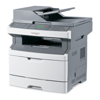
8. Remove the three screws securing the bracket (A) to the controller box assembly (B).
9. Remove the bracket (A).
10. Remove the four screws securing the bridge card assembly (C) to the bracket (A).
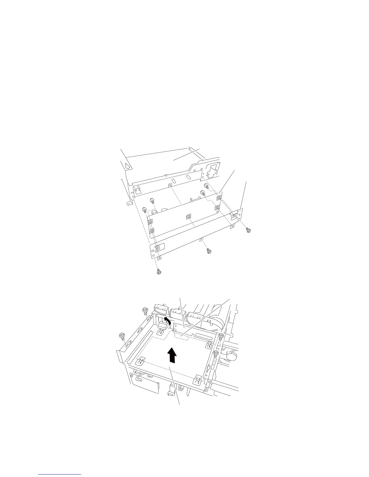
11. Remove the bridge card assembly (C).
Replacement warning: Ensure that the bridge card assembly (C) and the lower printer engine card (D) are
connected.
 Loading...