Repair information 4-91
7510
CMYK PC cartridge drive motor assembly removal
Warning: Ensure that all four PC cartridges are concealed from all sources of light, or damage will occur.
1. Remove the four PC cartridges from the machine.
2. Remove the rear cover assembly. See “Rear cover assembly removal” on page 4-5.
3. Remove the rear left middle cover. See “Rear left middle cover removal” on page 4-6.
4. Remove the rear upper cooling fan bracket assembly. See “Rear upper cooling fan bracket assembly
removal” on page 4-102.
5. Remove the developer / transfer roll HVPS card assembly. See “Developer / transfer roll HVPS card
assembly removal” on page 4-103.
6. Remove the lower printer engine card bracket assembly. See “Lower printer engine card bracket assembly
removal” on page 4-79.
7. Remove the 5V LVPS card bracket assembly. See “5V LVPS card bracket assembly removal” on page 4-86.
8. Remove the transfer belt drive motor assembly. See “Transfer belt drive motor assembly removal” on
page 4-82.
9. Remove the duplex unit assembly. See “Duplex unit assembly removal” on page 4-10.
10. Remove the fuser unit assembly. See “Duplex controller card assembly removal” on page 4-14.
11. Remove the MPF feed unit assembly. See “MPF feed unit assembly removal” on page 4-8.
12. Remove the developer / transfer roll HVPS card assembly. See “Developer / transfer roll HVPS card
assembly removal” on page 4-103.
13. Remove the 24V LVPS card bracket assembly. See “24V LVPS card bracket assembly removal” on
page 4-85.
14. Remove the CMYK transfer HVPS card assembly. See “CMYK transfer HVPS card assembly removal” on
page 4-94
15. Remove the K developer transport drive motor assembly. See “K developer / transport drive motor assembly
removal” on page 4-96.
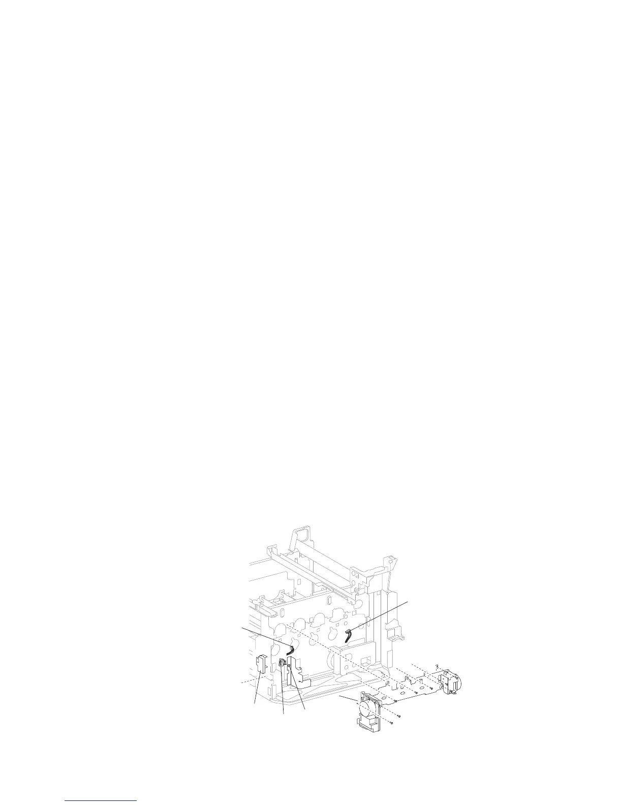
16. Remove the two connectors from the CMYK PC cartridge drive motor assembly (A).
17. Release the hook securing the access cover (B) to the machine.
18. Remove the access cover (B).
19. Remove the two screws securing the socket (C) to the machine.
20. Detach the socket (C) from the machine.
Note: The lower left screw can be accessed through the hole in the frame where the socket (B) was detached in
step 7.
21. Remove the eight screws securing the CMY PC cartridge drive motor assembly (A) to the machine.
22. When removing the CMYK PC cartridge drive motor assembly (A), ensure none of the harnesses become
damaged.
23. Remove the CMYK PC cartridge drive motor assembly (A).
Connector
A
Connector
B
C
Screwdriver
access hole
 Loading...