C-15
FX Series PLC User's Manual - Data Communication Edition
Parallel Link
3 System Configuration and Selection
3.2 Configuration of Each Group
A
Common Items
B
N:N Network
C
Parallel Link
D
Computer Link
E
Inverter
Communication
F
Non-Protocol
Communication
(RS/RS2 Instruction)
G
Non-Protocol
Communication
(FX
2N
-232IF)
H
Programming
Communication
I
Remote
Maintenance
Apx.
Discontinued
models
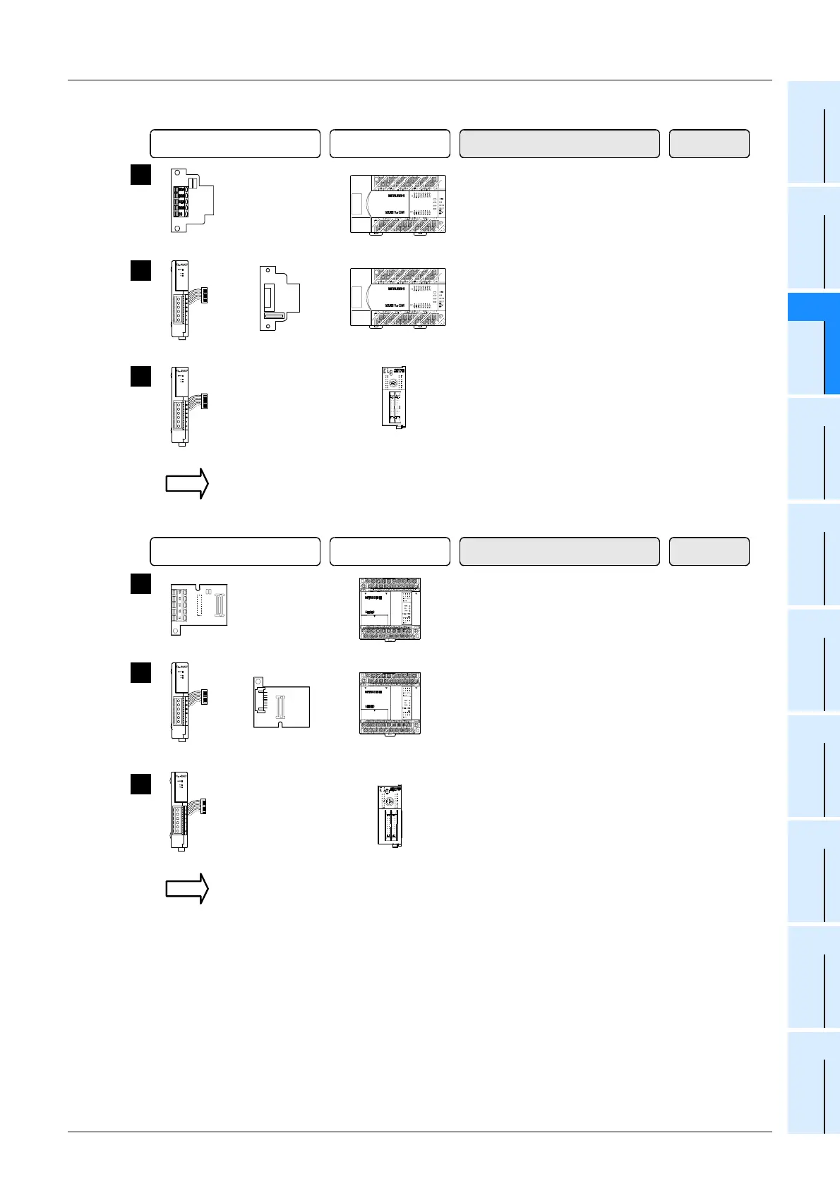
2. Group 2 (FX2N and FX2NC Series)
3. Group 3 (FX
1N and FX1NC Series)
Communication equipment operating
in accordance with RS-485
FX PLC Important point in selection
+
Communication
adapter
+
Special adapter
connection board
Attach the special adapter
connection board to the main unit,
and then attach the communication
adapter to the left side of the main
unit.
1
FX
2N
Series
+
Communication
adapter
Attach the communication adapter
to the left side of the main unit.
2
FX
2NC
Series
Total extension
distance
500 m
(1640' 5")
500 m
(1640' 5")
For communication equipment combinations for each FX Series, refer to the next section.
+
This is the communication board
built into the PLC, reducing the
installation area.
50 m
(164' 0")
FX
2N
Series
3
Communication
board
Communication equipment operating
in accordance with RS-485
FX PLC Important point in selection
Special adapter
connection board
+
Communication
adapter
+
Attach the special adapter
connection board to the main unit,
and then attach the communication
adapter to the left side of the main
unit.
2
FX
1N
Series
+
Communication
board
This is the communication board
built into the PLC, reducing the
installation area.
1
FX
1N
Series
Total extension
distance
500 m
(1640' 5")
50 m
(164' 0")
+
Communication
adapter
Attach the communication adapter
to the left side of the main unit.
3
FX
1NC
Series
500 m
(1640' 5")
For communication equipment combinations for each FX Series, refer to the next section.

 Loading...


