C-16
FX Series PLC User's Manual - Data Communication Edition
Parallel Link
3 System Configuration and Selection
3.2 Configuration of Each Group
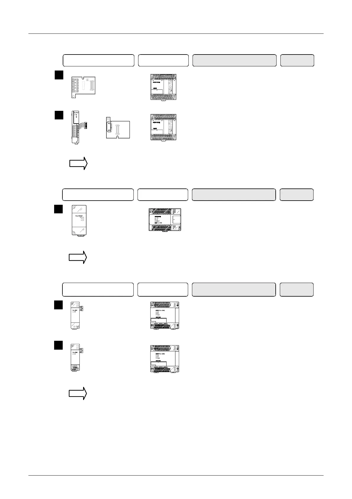
4. Group 4 (FX1S Series)
5. Group 5 (FX
0N Series)
6. Group 6 (FX
2(FX) and FX2C Series)
Communication equipment operating
in accordance with RS-485
FX PLC Important point in selection
+
Communication
adapter
+
Special adapter
connection board
Attach the special adapter
connection board to the main unit,
and then attach the communication
adapter to the left side of the main
unit.
2
FX
1S
Series
+
Communication
board
This is the communication board
built into the PLC, reducing the
installation area.
1
FX
1S
Series
Total extension
distance
500 m
(1640' 5")
50 m
(164' 0")
For communication equipment combinations for each FX Series, refer to the next section.
Communication equipment operating
in accordance with RS-485
FX PLC Important point in selection
Communication
adapter
+
Attach the communication adapter
to the left side of the main unit.
1
FX
0N
Series
Total extension
distance
500 m
(1640' 5")
For communication equipment combinations for each FX Series, refer to the next section.
Communication equipment using
optical fiber or in accordance
with RS-485
FX PLC Important point in selection
+
Communication
adapter
Attach the communication adapter
to the left side of the main unit.
Perform wiring using twisted pair
cables.
2
+
Communication
adapter
Attach the communication adapter
to the left side of the main unit.
Perform wiring using optical fiber
cables.
1
FX
2
(FX)/FX
2C
Series
Total extension
distance
10 m
(32' 9")
50 m
(164' 0")
For communication equipment combinations for each FX Series, refer to the next section.
FX
2
(FX)/FX
2C
Series

 Loading...


