MOOG
ID
No.: CB40859-001 Date: 02/2018
MSD Servo Drive- Device Help
128
7 Control
ID Index Name Unit Description
371 0 CON_IP_RefTF ms
304 0 ms
2939 0 ms
325
325 0 Hz
325 1 Hz
325 2 Hz
325 3 Hz
326 0
327
CON_SConTS
CON_SCON_TorqueTF
Digitalfilter
CON_SCON_FilterFreq
CON_SCON_FilterFreq
CON_SCON_FilterFreq
CON_SCON_FilterFreq
CON_SCON_FilterFreq
CON_SCON_FilterAssi
CON_SCON_FilterPara
327 0
Speedreferencefiltertimeconstant(SCON
mode)
Speedcontrolsamplingtime
Actualtorquefiltertime
Digitalfilter/speedcontrollersettings
Filterfrequenciesofdigitalfilter
1stcenter/cutoff
1stwidth
2ndcenter/cutoff
2ndwidth
Digitalfilterdesignassistant
Coefficientsofdigitalfilter
b0*x(k)
327 1
327 2
327 3
327 4
327 5
327 6
327 7
327 8
FilterParab0
FilterParab1
FilterParab2
FilterParab3
FilterParab4
FilterParaa1
FilterParaa2
FilterParaa3
FilterParaa4
b1*x(k-1)
b2*x(k-2)
b3*x(k-3)
b4*x(k-4)
a1*y(k-1)
a2*y(k-2)
a3*y(k-3)
a4*y(k-4)
1550 0
1551 0
1552
1552 0 Hz
1552 1
SCD_NotchType
SCD_NotchCntl
SCD_NotchFreq
SCD_NotchFreq
SCD_NotchLambda Hz/min^-
2
AdaptiveNotchfilter:Method
AdaptiveNotchfilter:Controlword
AdaptiveNotchfilter:Frequencies
AdaptiveNotchfilter:Frequency
AdaptiveNotchfilter:Coefficient
1552 2 Hz
1552 3 Hz
1552 4
SCD_NotchMinFreq
SCD_NotchMaxFreq
SCD_NotchDeltaFreq Hz
401 0 Nm(N)
402 0 1/min
AdaptiveNotchfilter:Min.frequency
AdaptiveNotchfilter:Max.frequency
AdaptiveNotchfilter:Maximumfrequency
change(ineachiteration)
Advancedanalysisofthespeedcontroller
Additivetorquereference
Additivespeedreferencevalue(withoutramp)
AnalysisofSpeedcontrol
CON_SCON_AddTRef
CON_SCON_AddSRef
Scopesignals(advanced)
Observer
Scopesignals(basic)
Table 7.10: “Speed controller” parameter (continue)
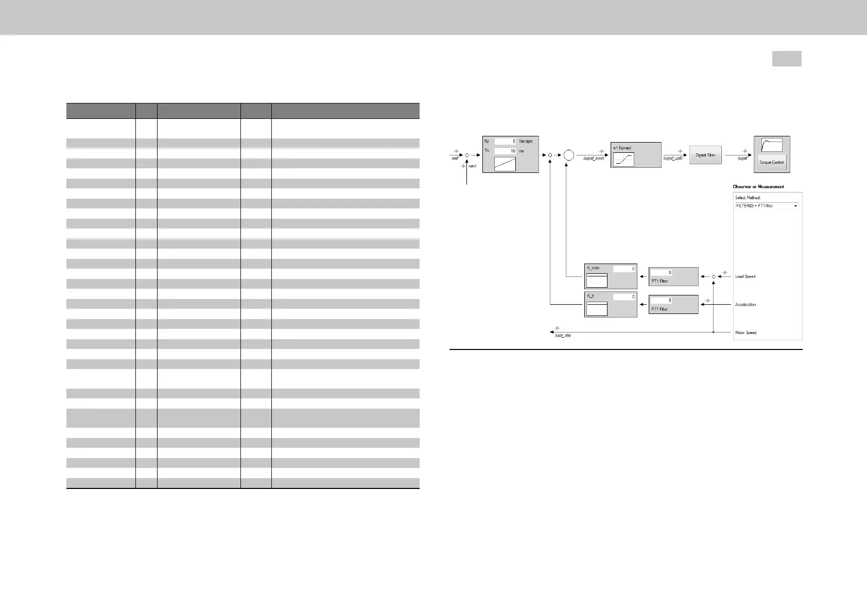
7.4.1Advancedspeedcontrol
Fig. 7.21: “Speed controller advanced setup” dialog box
7.4.1.1Observer
The phase shifts over time in the feedback branch generate high-frequency noise as
well as high-frequency resonances. The single-mass observer reduces these high-
frequency interference and increases the control dynamism.
The function of the observer is based on the mathematical description of the
controlled system which calculates the trend over time of the state variables under
the influence of the input variables. The difference between the measured and the
estimated state variables is fed back to the estimated state variables via a feedback

 Loading...