5.6.1Synchronousmotoridentification(rotaryandlinear)
Enterthemotordata.
Click"Identification"button
Currentcontrollertuning:optimization of the current controller is done
automatically.
5.6.2Asynchronousmotoridentification
Currentcontrollertuning
Measurementof:P 470[0] - MOT_Rstat:Statorresistance,P 476[0] - MOT_
Rrot:Rotorresistance,P 471[0] - MOT_Lsig:Leakageinductance
MaximumeffectivecurrentIdmaxP 474[0] - MOT_LmagIdNom
Calculationoftheworkingpoint:P 462[0] - MOT_FluxNom:Nominalflux,
P 340[0] - CON_FM_Imag:Magnetizingcurrent
Calculationof:Current,speed,andpositioncontrolparameters
Clickthe"Startcalculation"buttontodeterminetherotorresistanceP 476[0] -
MOT_RrotandleakageinductanceP 471[0] - MOT_Lsig.
Measurementofthesaturationcharacteristic(tablevaluesforstator
inductanceP 472 - MOT_LSigDiff);
Measurementsaretakenuptofourtimesratedcurrent,providedthe
power
stagecurrentpermits it at standstill.Ifthisisnotthe
case,themeasurementis
madeusingacorrespondinglysmallercurrent.
P 340[0] - CON_FM_ImagMagnetizingcurrent
MOOG
ID
No.: CB40859-001 Date: 02/2018
MSD Servo Drive- Device Help
45
5 Motor
5.7SupportformotorfilterswhenusingPMSM
motors
5.7.1Generalfunctionaldescription
In applications involving high-speed drives in particular, the use of filters between
the inverter output and the motor is widespread as a measure designed to attenuate
current harmonics. The following two are used for this purpose:
Motorchokes
LCfilters,alsoreferredtoas“sinewavefilters”
A motor choke basically increases the stator inductance and, in the case of current-
controlled drives, simply results in a higher inductive voltage consumption.
Accordingly, it is not necessary to take motor chokes into account separately when
calculating current setpoints.
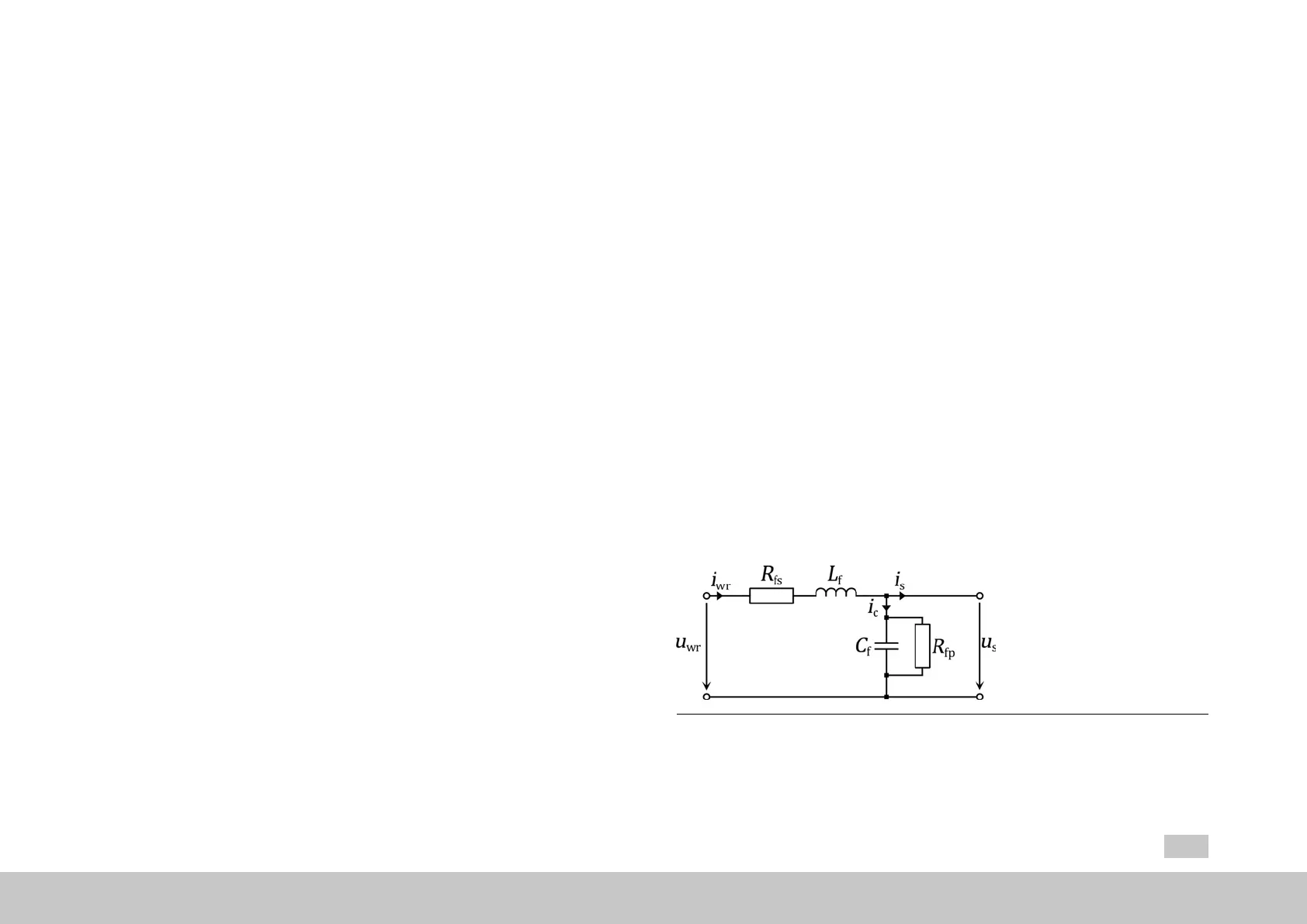
Meanwhile, as a result of the additional capacitor current (
i
c
) resulting from their use,
sine wave filters result in a change to the current vector between the inverter output
(
i
inv
) and the motor (
i
s
). Accordingly, these filters must be taken into account when
calculating current setpoints in order to ensure that the motor will be run at the
desired operating point (normally with q current operation) at all speeds.
Fig. 5.14: Single-phase equivalent circuit diagram for a sine wave filter

 Loading...