Referencevalue
P 0165
-OFF (0)
-ANA0 (1)
-ANA0 (2)
-Tab (3)
-leer (4)
-iPLC (5)
-PARA (6)
-CiA DS402 (7)
-SERCOS (8)
-PROFIBUS (9)
-VARAN (10)
Normalization
-DS402
-SERCOS
-User-specific
Profilegenerator
PG-Mode
-Ramps
-Smoothing
-Filter
Referencevalue
speedcontrol
Referencevalue
Userunit
Referencevalue
Increments
Fig. 8.25: Profile mode speed control
Profile Generator with speed control:
ControlmodeP 300[0] - CON_CfgCon =speedcontrol
UnderProfileselecttheprofilegenerator(PG)P 301[0] - CON_Ref_Mode =
PG(0)
Selectionofreferencesource/>P 165[0] - MPRO_REF_SEL
Scaling
Selectjerkconditions
Setstopramps,smoothing,filter,homing
MOOG
ID
No.: CB40859-001 Date: 02/2018
MSD Servo Drive- Device Help
181
8 Motion profile
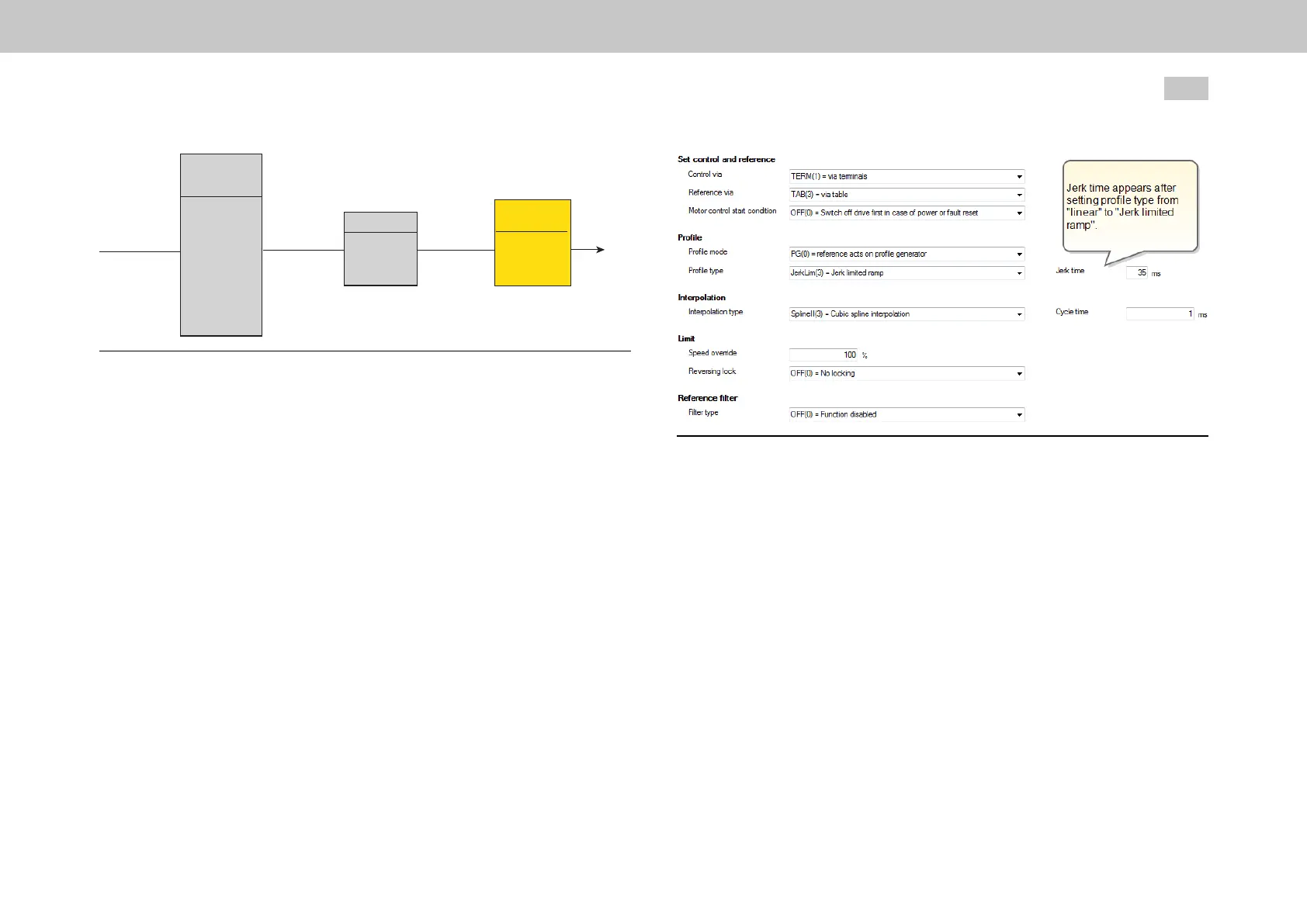
Fig. 8.26: Speed control in PG mode, smoothing
8.3.2PGmodewithpositioncontrol
Travel commands are transmitted to the internal profile generator (see
Section "Basic settings" on page 180). It is composed of the following items:
Targetposition
Maximumtravelspeed
Maximumacceleration
Maximumdeceleration
TheprofilegeneratorusestheP 166[0] - MPRO_REF_JTIMEjerkvalues
andaP 167[0] - MPRO_REF_OVRoverridefactorforthetravelspeedin
ordertogeneratethetrajectoryforthepositionsetpointthatwilltaketheleast
amountoftime,takingalllimitationsintoaccount.
Thepositionreferencesarethenprocessedwiththeselectedinterpolation
method.

 Loading...