8.5.6Methods(-7)to(0)
8.5.6.1Homingmethodforincrement-codedencoders
Method(-6):Movementinnegativedirection
Method(-7):Movementinpositivedirection
See Section "Distance-coded reference marks" on page 101 as well.
8.5.6.2Method(-5):Absoluteencoder
These homing methods are suitable for absolute encoders (e.g. SSI multi-turn
encoders). Homing will be carried out immediately after the mains is on. The
reference position is calculated on the basis of the encoder absolute position plus
zero offset. In the case of a SSI multi-turn encoder, homing with zero point offset = 0
gives the absolute position of the SSI encoder. Referencing again without changing
the setting for the zero point offset does not cause a change of the position. To set
the machine reference point homing method (-12) should be used.
8.5.6.3Method(-4)andmethod(-3):Notdefined
8.5.6.4Method(-2):Nohoming
No homing will be performed. The zero point offset is added to the current position.
When the power stage is first switched on, “Homing completed” is set as the status.
This method is suitable for absolute encoders, provided that no offset compensation
is required. For an offset compensation, please select method (-5).
8.5.6.5Method(-1):Actualposition=0
The actual position corresponds to the zero point; it is set to 0, meaning the drive
performs an actual position reset. The zero offset will be added.
MOOG
ID
No.: CB40859-001 Date: 02/2018
MSD Servo Drive- Device Help
194
8 Motion profile
8.5.7Method(1)andmethod(2):Limitswitchandzero
pulse
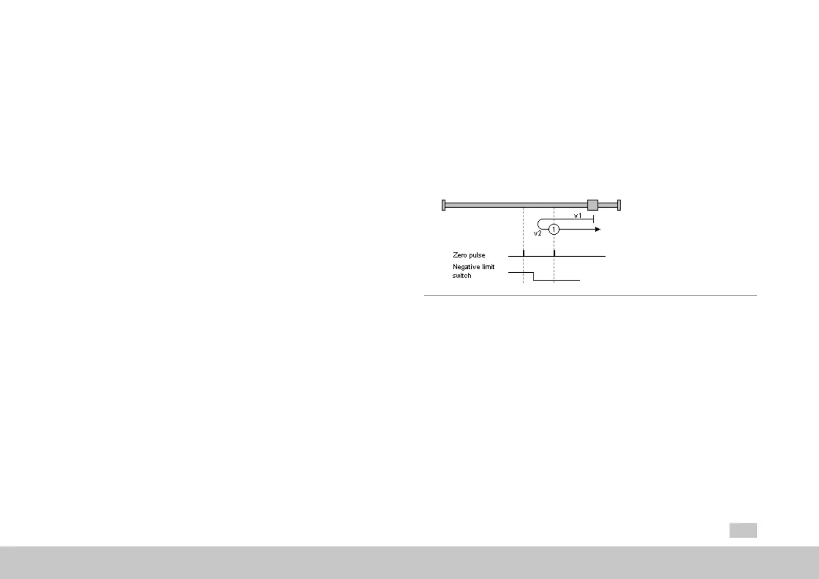
8.5.7.1Method1:Negativelimitswitchandzeropulse
Startmovementleft;atthistimethehardwarelimitswitchisinactive.
Thedirectionofmovementreversesonanactivehardwarelimitswitchedge.
Firstzeropulseafterfallinglimitswitchedgecorrespondstozero/reference
point.
Fig. 8.45: Negative limit switch and zero pulse
8.5.7.2Method2:Positivelimitswitchandzeropulse
Startmovementright;atthistimethehardwarelimitswitchisinactive.
Thedirectionofmovementreversesonanactivehardwarelimitswitchedge.
Firstzeropulseafterfallinglimitswitchedgecorrespondstozero/reference
point.

 Loading...