MOOG
ID
No.: CB40859-001 Date: 02/2018
MSD Servo Drive- Device Help
140
7 Control
ID Index Name Unit Description
342 5 %
342 6 %
342 7
CON_FM_SpeedTab
CON_FM_SpeedTab
CON_FM_SpeedTab %
343 Magnetizingcurrentscalingvs.speed
343 0 %
343 1 %
343 2 %
343 3 %
343 4 %
343 5 %
343 6 %
343 7 %
343 8 %
343 9 %
343 10 %
343 11 %
343 12 %
343 13 %
343 14 %
343 15 %
344 0 ms
345 0 A/V
346 0
CON_FM_ImagTab
CON_FM_ImagTab
CON_FM_ImagTab
CON_FM_ImagTab
CON_FM_ImagTab
CON_FM_ImagTab
CON_FM_ImagTab
CON_FM_ImagTab
CON_FM_ImagTab
CON_FM_ImagTab
CON_FM_ImagTab
CON_FM_ImagTab
CON_FM_ImagTab
CON_FM_ImagTab
CON_FM_ImagTab
CON_FM_ImagTab
CON_FM_ImagTab
CON_FM_VConTF
CON_FM_VConKp
CON_FM_VConTn ms
347 0 CON_FM_VRef %
348 0 %
435 0
CON_FM_SlipCon
CON_FM_FWMode
436 0 %
437 0 %
438 0
CON_FM_FWSpeedScale
CON_FM_FWCurrScale
CON_FM_
FWMaxBackEMF
V
Voltagecontrolfiltertimeconstant
Voltagecontrolgain
Voltagecontrolintegrationtimeconstant
Voltagecontrolreference(Relativetomax.
voltage)
Slipcontrolgainforfieldweakening
Modeoffieldweakening/d-currentcalculation
(PSM)
Speedscalingforfieldweakening(tablemode)
q-currentscalingforfieldweakening(tablemode)
Maximumback-EMFinfieldweakeningmode
(DClinkvoltage)
Table 7.22: “Field-weakening” parameters (continue)
ID Index Name Unit Description
421 CON_FM_FWTabIdx
421 0
421 1
422 0 A
423 0
CON_FM_FWTabIdx
CON_FM_FWTabIdx
CON_FM_FWTabId
CON_FM_FWTabIq A
Tableindexforfieldweakening/reluctance
torqueutilization
Speedindex
Torqueindex
d-currenttableentry
q-currenttableentry
Table 7.23: “Field weakening - Interior permanent magnet synchronous motor
(IPMSM)” parameters
7.6.4Field-weakeningofasynchronousmotorvoltage
controller
The voltage controller is superimposed onto the selected characteristic curve. When
the voltage controller is used, a part of the available voltage is used as a control
reserve. The more dynamic the operation, the more control reserve is required. In
this case it may be that the voltage for rated operation is not sufficient, and also that
the controller starts to oscillate.
The PI voltage controller can be optimized by adaptation of the gain P345[0] -
CON_FM_VConKp, integral-action time P346[0] - CON_FM_VConTn and filter time
constant for motor voltage feedback P344[0] - CON_FM_VConTF. P347[0] - CON_
FM_VRef sets the voltage reference, though the threshold needs to be reduced in
response to rising demands as this maintains a kind of voltage reserve for dynamic
control processes.
A certain voltage reserve is necessary for stable operation. It is specified by way of
P347[0] - CON_FM_VRef (< 100%). The value should be set high (≤ 90%) where
there are high demands in terms of dynamic performance. When using a lower
dynamic performance instead, the maximum achievable torque can be optimized in
relation to the current by using higher values (> 90%).
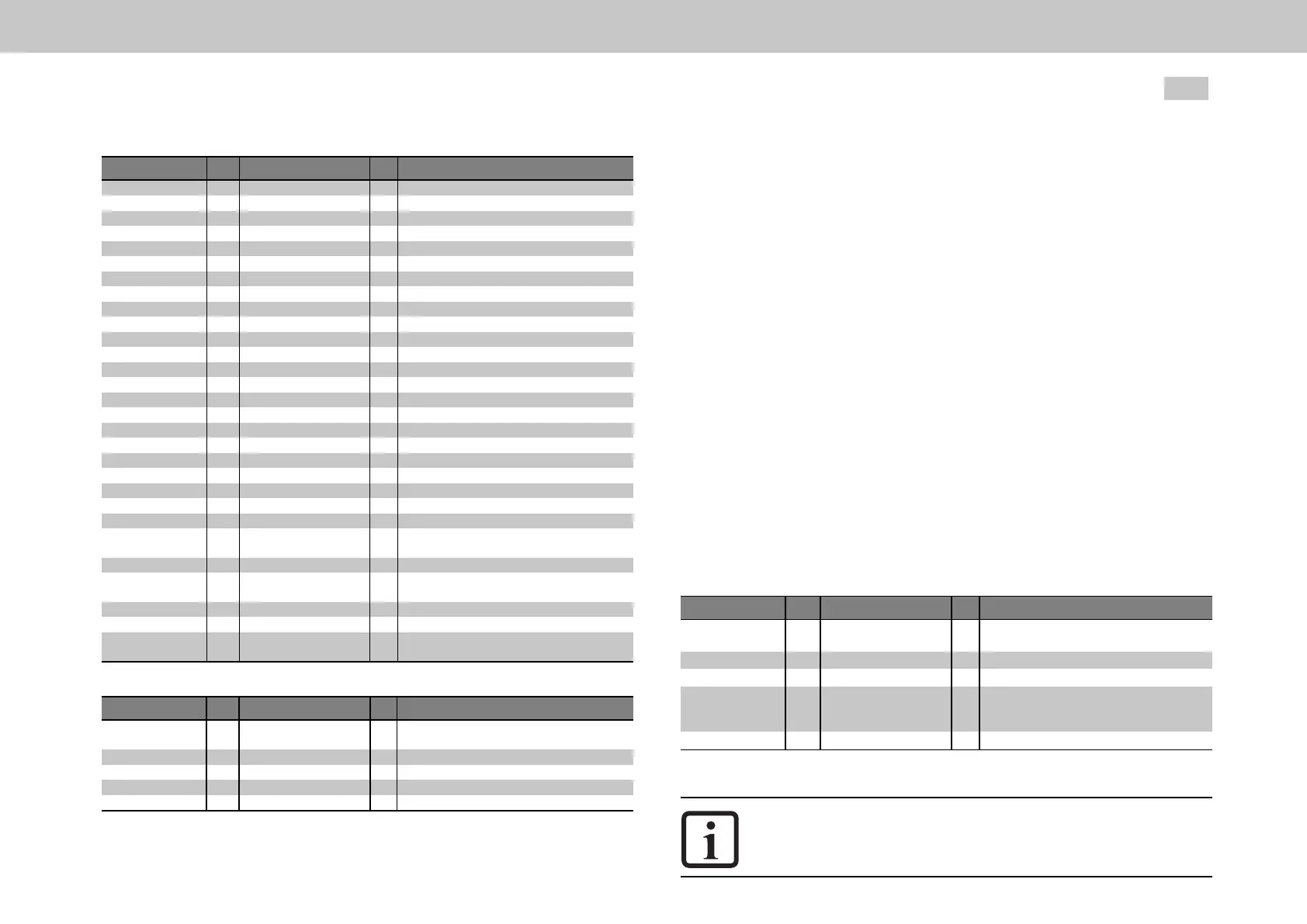
P No. Index Name Unit Description
344 0 CON_FM_VConTF ms Timeconstantofvoltagecontrolleractualvalue
filter
345 0 CON_FM_VConKp A/V VoltagecontrollergainfactorKp
346 0 CON_FM_VConTn ms Voltagecontrollerintegral-actiontimeTn
347 0 CON_FM_VRef % Voltagecontrollerreference(as%ofthecurrent
DClinkvoltage)Ifthevalue0%isset,the
controllerisnotactive.
458 0 MOT_SNom rpm Motorratedspeed
Table 7.24: “Voltage controller” parameters
NOTE
Ifthecontrolreserveistoosmall,theServocontrollertypically
shutsoffwithanovercurrenterror.

 Loading...