ID Index Name Unit Description
PThreshold
186 MPRO_ANA1_TRamp ANA1:Torquemodeacceleration[0]and
deceleration[1]
186 0 MPRO_ANA1_TRamp Nm/s
186 1 MPRO_ANA1_TRamp Nm/s
187 MPRO_ANA1_SRamp ANA1:Speedmodeacceleration[0]and
deceleration[1]
187 0 MPRO_ANA1_SRamp SPEED/s
187 1 MPRO_ANA1_SRamp SPEED/s
Table 8.27: “Analog channel ISA01” parameters (continue)
MOOG
ID
No.: CB40859-001 Date: 02/2018
MSD Servo Drive- Device Help
215
8 Motion profile
8.9Statemachine
The system state of the drive is basically managed by the central state machine
according to CiA 402. However, the transitions and states which the state machine
passes through are dependent on the drive profile setting and the bus system used.
During operation, a distinction is made between drive standstill, operation, and the
error states.
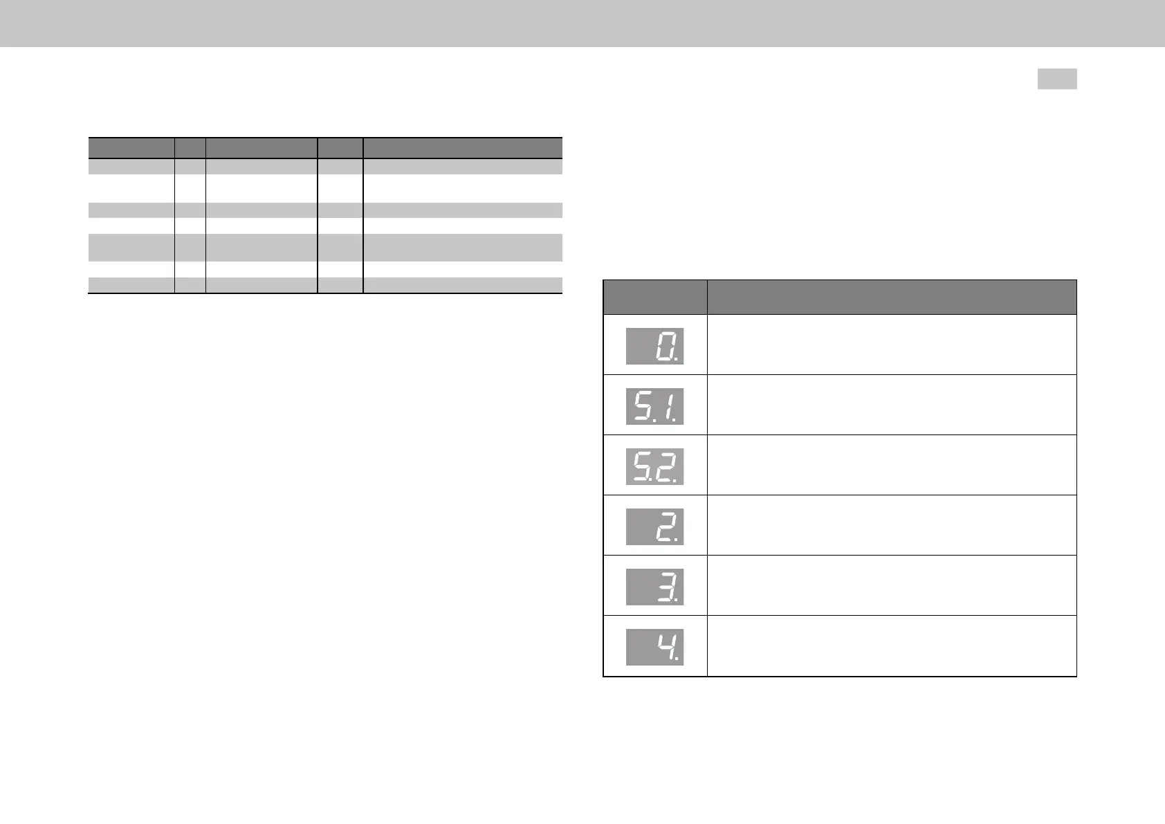
Display System state
Initializationondevicestartup
Notreadyforstarting(theDClinkvoltagemaybetoolow)
Startinhibit(DClinkvoltagepresent,powerstageoff)
Startinglockout
Readyforstart
Controlinitialization:Autocommutation,fluxbuild-up,etc.
Table 8.28: Central state machine according to CiA 402 - device display

 Loading...