ID Index Name / Setting Unit Description
Channel3
8 ENCPOS_CH3_INC(8)=Encoderposition
Channel3inincrements
9 ENCPOS_CH4(9)=Encoderposition
Channel4
10 ENCPOS_CH4_INC(10)=Encoderposition
Channel4inincrements
11 ACTPOS2(11)=Actualpositionofredundant
encoderinuserunits
12 SERCOS(12)=ReferredtoSERCOSprofile
parametersS-x-0426,S-x-0427
13
1402 0 MPRO_TP_Channel
1402 1 MPRO_TP_Channel
1402 2 MPRO_TP_Channel
1404 MPRO_TP_Lines Touchprobe:Lines@pulsecounteron
channelx
1404 0 MPRO_TP_Lines
1404 1 MPRO_TP_Lines
Table 8.29: “Touch probe” parameters (continue)
NOTE
Formoreinformationrefertothebussystemusermanualsorthe
descriptionoftheMSDPLC.
MOOG
ID
No.: CB40859-001 Date: 02/2018
MSD Servo Drive- Device Help
218
8 Motion profile
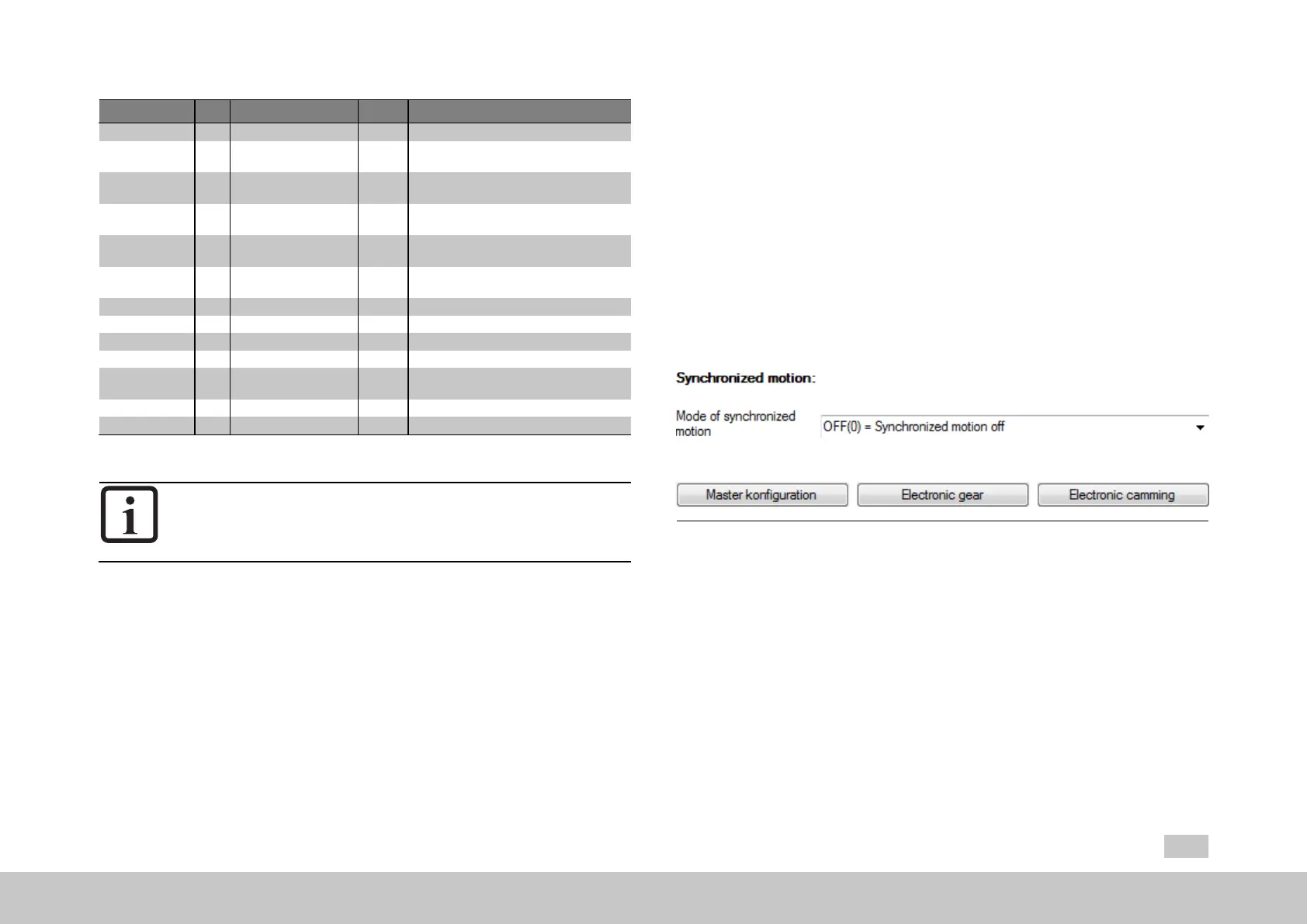
8.11Synchronizedmotion
The Synchronized Movement function enables synchronous running of the drive in
relation to a real or virtual master axis.
Digital control signals are used to provide positionally precise disengagement from
the guide value (e.g. with standstill at cycle end) and positionally precise
engagement to the current guide value.
In the master configuration, there are three options when selecting the master
encoder: an encoder system, the virtual master, or the parameter interface. If the
parameter interface to a bus system (control and setpoint basic settings) is used, the
control will be configured via a bus system.
Fig. 8.71: “Synchronized motion” screen
There are various modes available in the “synchronization mode” drop-down menu
(P242[0] - MPRO_ECAM_SyncModMode):
Off(0)=Synchronizedmotionoff
ECAM_iPlc(1)=Electr.CamplateviaMSDPLC
EGEAR_iPlc(2)=Electr.GearingviaMSDPLC
ECAM_PARA(3)=Electr.Camplateviaparameter
EGEAR_PARA(4)=Electr.Gearingviaparameter

 Loading...