Dependingontheconfiguredfunction,the“Options...”buttonmaybecome
enabled.Ifitis,thisbuttoncanbeusedtoswitchtoadifferentscreendirectly
anddefinethefunction’sexactbehaviourthere.
Therelayoutputcanbeswitchedfrom“active-high”to“active-low”(bit8in
P 142[0] - MPRO_OUTPUT_INV).
NOTE
RelayoutputRELOUT2(P 127[0] - MPRO_OUTPUT_FS_
RELOUT2)outputsthestatusoftheSTOfunction.Accordingly,itis
setto"SH_S"andcannotbechanged.Becauseofthis,thisoutput
willnotbeshownonthescreen.
Forbasicinformation,aswellasmandatoryplanning,wiring,
commissioningandtestingrequirementsfortheSTOfunction,see
the“STOsafetyfunctiondescription”fortheMSDServoDrive
Single-AxisSystem,MSDServoDriveMulti-AxisSystemand
MSDSingle-AxisServoDriveCompact(IDNo.:CB19388).
ID Index Name Unit Description
126 0 MPRO_OUTPUT_FS_
RELOUT1
FunctionofdigitaloutputRELOUT1
127 0 MPRO_OUTPUT_FS_
RELOUT2
Functionofdig.outputRELOUT2isfixedat
'SafetyHold'
142 0 MPRO_OUTPUT_INV Outputinv.OSD0-2(0-2),MBRK(6),REL1/2
(7/15),OED0-7(16-23)
Table 9.9: “Relay outputs” parameters
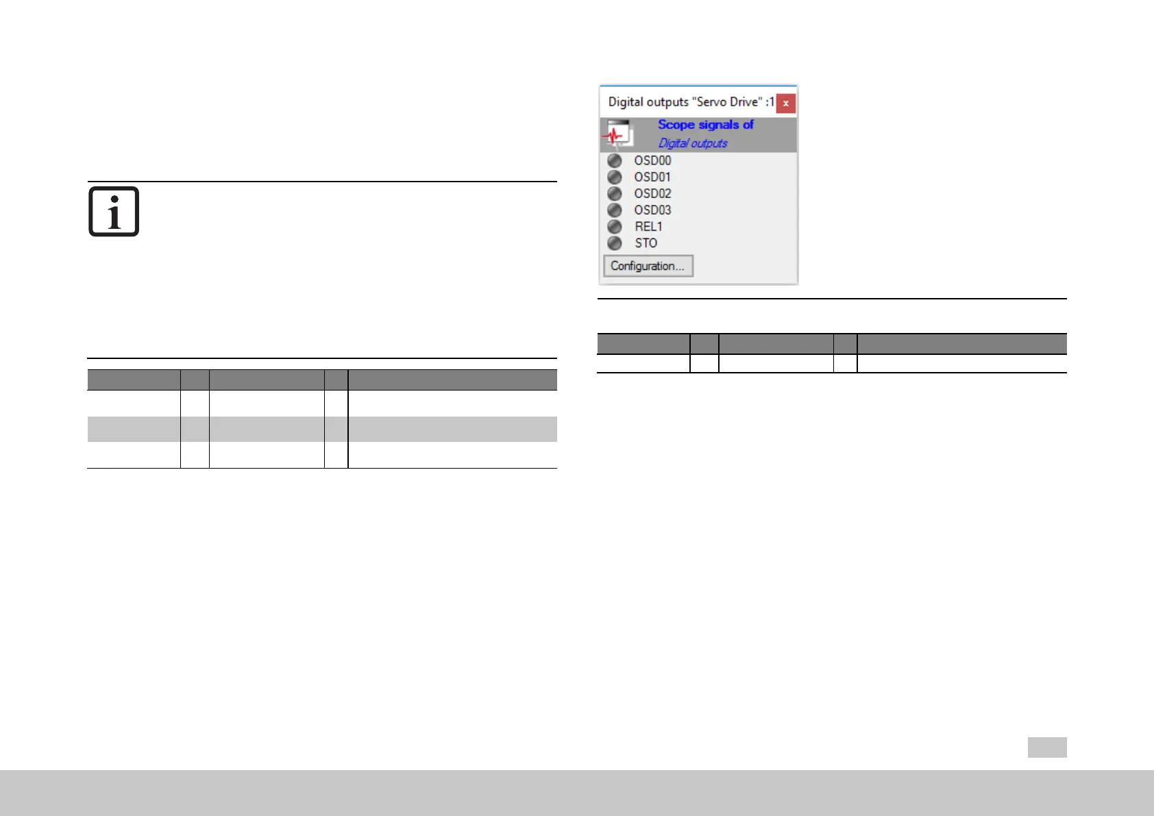
9.3.4Statusofdigitaloutputs
Clicking on the “Status of digital outputs” field on the input screen for the digital
outputs will open a visualization showing the digital outputs’ states.
MOOG
ID
No.: CB40859-001 Date: 02/2018
MSD Servo Drive- Device Help
241
9 Input/Output settings
Fig. 9.6: “Status of digital outputs” dialog box
ID Index Name Unit Description
143 0 MPRO_OUTPUT_STATE Dig.Outputs:Status
Table 9.10: “Status of digital outputs” parameters
9.3.5ReferencereachedREF(6)
If a digital output is set to “REF(6) = Target reached / Reference reached” for torque
and speed control as well as positioning, a range can be defined in which the actual
value may deviate from the reference without the "Reference reached REF(6)"
message becoming inactive. Reference value fluctuations caused by reference input
are thus taken into account.

 Loading...