5.3Linearsynchronousmotor
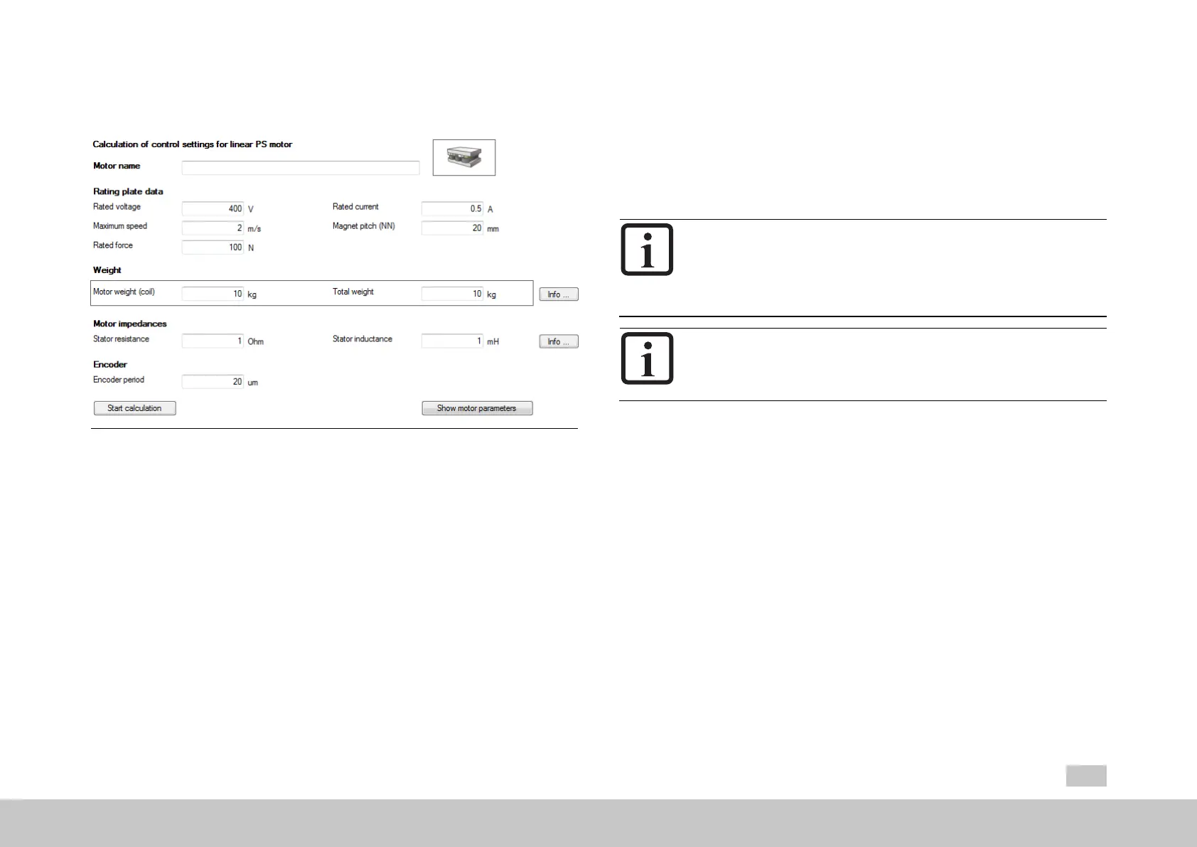
Fig. 5.4: “Linear synchronous motor settings” screen
There are two methods of creating a motor data set for the linear synchronous motor.
Variant1:Motorcalculation
Variant2:Motoridentification(see Section"Motoridentification"onpage 43)
Variant 1: Motor calculation
Entermotordata
Themotordatarelevanttothecalculationmustbeenteredfromthedata
sheet.
Clickon“Startcalculation”.
MOOG
ID
No.: CB40859-001 Date: 02/2018
MSD Servo Drive- Device Help
35
5 Motor
IfthemomentofinertiaofthemotorP 461 - Mot_Jisnotknown,avalue
roughlycorrespondingtothemotor'smomentofinertiamustbeapplied.
The calculation process can be monitored in theMoogDRIVEADMINISTRATOR
via the menu,View, Messages.
Calculationofoperatingpoint:FluxP 462 - MOT_FLUXNom
Calculationof:current,speedandpositioncontrolparameters
NOTE
P 490 - MOT_ISLinRot =LIN(1):Theparameterwillautomatically
setthenumberofmotorpolepairstoP 463 - Mot_PolePairs =1.
Asaresult,aNorthtoNorthpolepitchcorrespondstoonevirtual
revolution(P 49 - Mot_MagnetPitch).
NOTE
Allexistingmotorparametersareoverwritten.
Calculated values
Translationofthelinearnominalquantitiesintovirtualrotarynominal
quantities
Defaultvaluesforautocommutation
Encoderlinespervirtualrevolution
Fluxsettings(includingfortorqueconstant)
ControlsettingsforPIcurrentcontroller:Thecurrentcontrolleris
dimensionedbasedontheactual switchingfrequencyset.
PIspeedcontrollerandpositioncontrollergain:A moderately rigid
mechanism and moment of inertia matching from load to motor with a ratio
of 1:1 is assumed here.
Thedefaultvalueforspeedtrackingerrormonitoringcorrespondsto50%of
the nominal speed.
V/Fcharacteristic

 Loading...