Select from database
Clicking on this button will open a menu that can be used to select encoders. The
data sets for Moog encoders will already be available there by default.
Encoder name
You can use this field to enter your own information for describing the encoder
(maximum 31 characters) (P555[0] - ENC_CH1_Info).
Cyclic position via
This drop-down menu is used to select the “main interface” (P505[0] - ENC_CH1_
Sel).
Pulses per revolution
As soon as SINCOS(1), TTL(3) or HALL(5) is selected as the “main interface,” this
field will appear so that you can enter the number of analog Sin/Cos lines per
revolution (TTL lines as well).
Absolute interface
This drop-down menu is used to select the “auxiliary interface” (P540[0] - ENC_
CH1_Abs).
NOTE
Selectingan“auxiliaryinterface”isredundantif,forexample,SSI
(2)isselectedasthe“maininterface”(correspondstocyclical
evaluationviaSSI).Inthiscase,theabsolutevalueinitialization
willalsobecarriedoutviatheSSIinterface,regardlessofthe
selected“auxiliaryinterface”.
Gear ratio
These fields can be used to define a gear ratio for the encoder (in the output side).
For details, see Section "Encoder gearing" on page 87.
MOOG
ID
No.: CB40859-001 Date: 02/2018
MSD Servo Drive- Device Help
57
6 Encoder
Signal correction (GPOC)
GPOC is a special Moog online process for improving the quality of Sin/Cos
signals before they are used to calculate a position. If “SINCOS(1)” is selected as
the “main interface,” this process may be useful. For details, see Section "Signal
correction GPOC (Gain Phase Offset Correction)" on page 71.
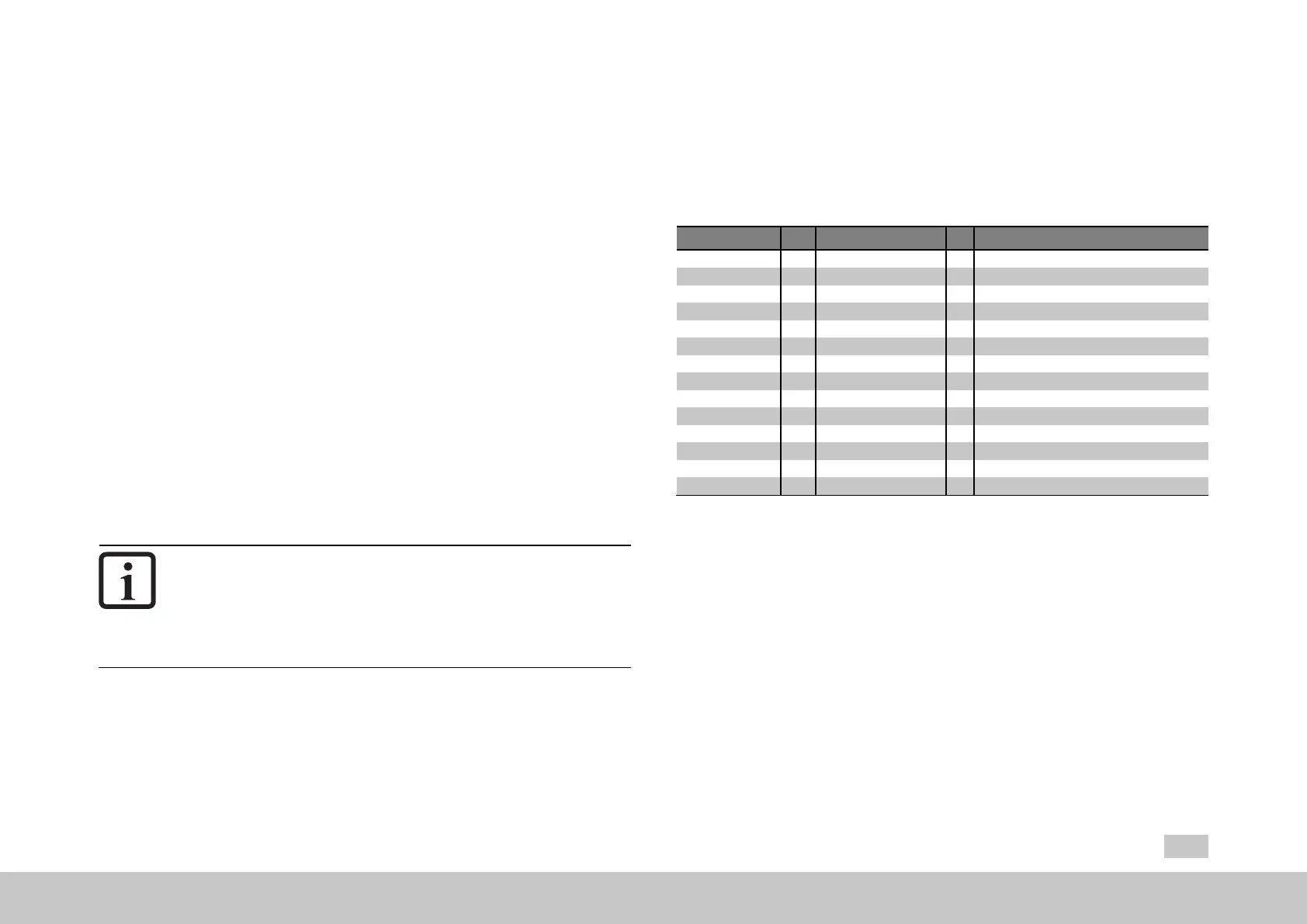
P No. Index Name / Settings Unit Description
505 0 ENC_CH1_Sel Encodertypeselection
OFF(0) Functiondisabled
SINCOS(1) Sin/Cosencoder
SSI(2) DigitalSSIencoder
TTL(3) TTLencoder
EnDat(4) DigitalEnDatencoder(2.1or2.2)
HALL(5) DigitalHallsensor
540 0 ENC_CH1_Abs Absolutepositioninterfaceselection
OFF(0) Noadditionalabsolutevalueinterface
SSI(1) SSIinterface
ENDAT(2) EnDatinterface
HIPER(3) HIPERFACE®interface
SSI_CONT(4) SSI-interfacewith1mscontinuousclock
555 0 ENC_CH1_Info Encoderinformation
Table 6.5: Channel Ch1 encoder configuration (X7) parameters
6.5.1MainparametersforencoderchannelCh1
The following table lists the most important parameters for the Ch1 encoder channel.
These parameters are then described in the chapters for selecting a special encoder
with P505[0] - ENC_CH1_Sel and P540[0] - ENC_CH1_Abs.
Someoftheparametersareself-explanatory,suchasLines,MultiTand
SingleT.

 Loading...