MOOG
ID
No.: CB40859-001 Date: 02/2018
MSD Servo Drive- Device Help
131
7 Control
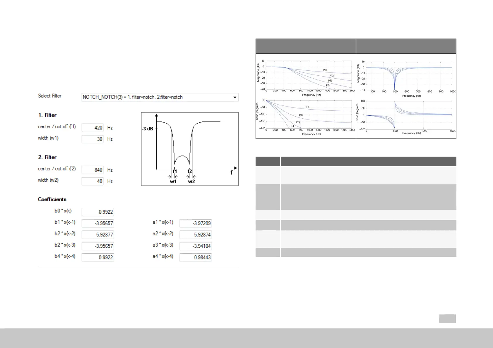
7.4.2Digitalfilter
To filter any noise on the actual speed value, or to damp resonance frequencies,
various filter combinations can be used. A range of filter variants are available. The
coefficients of the transfer function are automatically determined as soon as the
values for the middle and limit frequency and the width have been entered.
Fig. 7.24: “Speed controller - Digital filter” dialog box
Bode diagrams PT1 to PT4
Bode plots for band-stop filters (notch
filters)
Table 7.12: Filter Bode plots
No. Action
1
Scope setting: isq (unfiltered, torque-forming current) Set shortest
sampling time Create scope plot without notch filtering
2
On the oscilloscope click the "Mathematical functions" > FFT (Fourier
analysis) icon. From the following pop-up menu choose isq. Disturbance
frequency is displayed.
3
Select filter
4
Enter middle/limit frequency
5
Width: Enter the bandwidth of the limit frequency; the width has no effect
when using PTx filters
6 Createscopeplotwithnotchfiltering
Table 7.13: Instructions for FFT signal analysis

 Loading...