P 347
CON_FM_VRef
Available Uzk
vmot
soll
vmot_filt
P 345
P 346
vreg_isdref
sdrefmod
isdref [1/n]
Ti
d-current control
1
P 344
Tf
Vmot
udref
uqref
Voltage
Calculation
Kp
Tn
x
2
x
y
Voltage control
y
2
CON_FM_ImagSLim
P 341
0
i
q
ω
e
u
zk
+
characteristic isd=f(n)
i
P 0435
CON_FM_FWMode
off
2
1
calculated map
sdref_tab
i
+
0
√2 * P 340 CON_FM_Imag
Variant 2:
Variant 1:
0
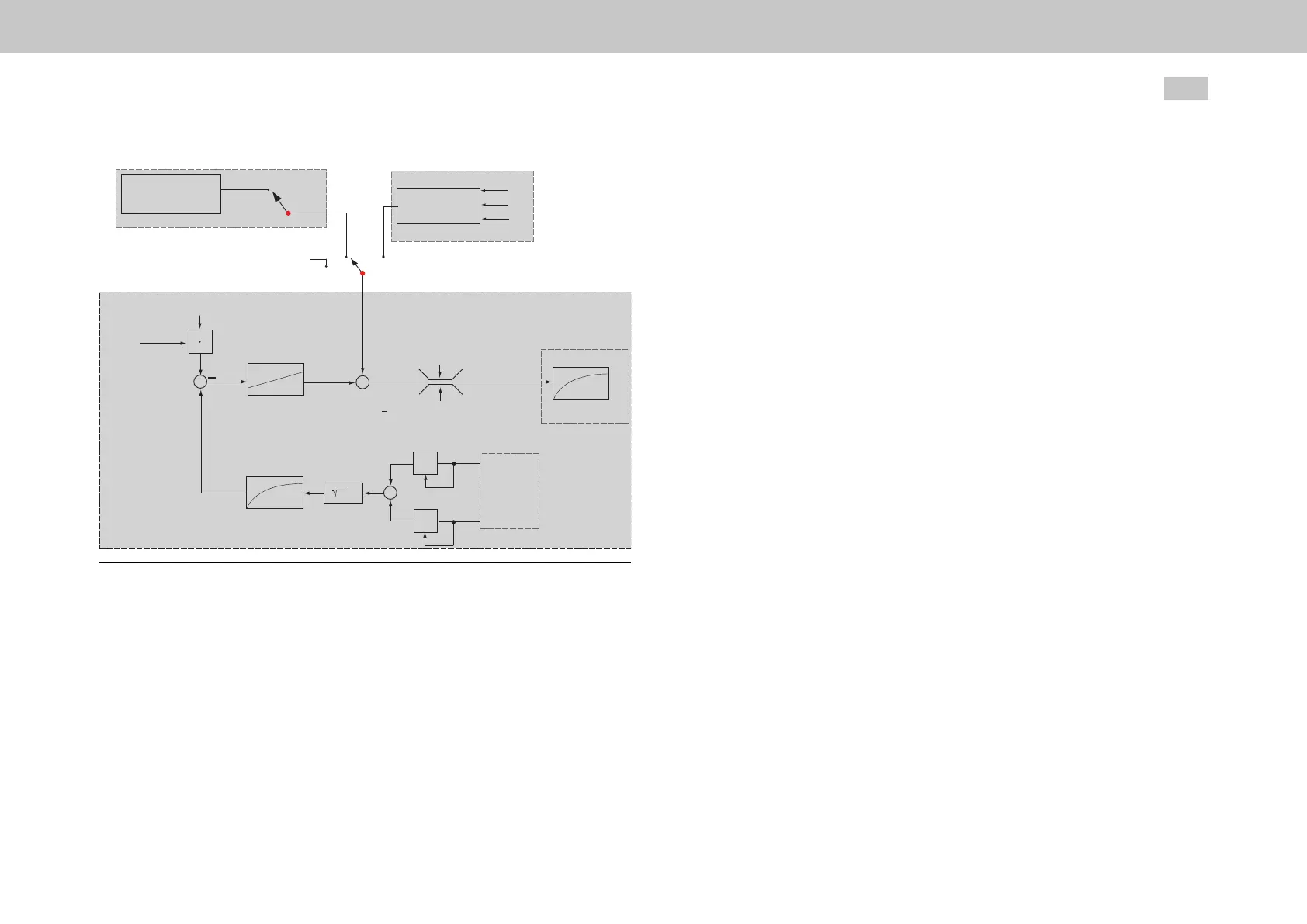
Fig. 7.33: Field weakening diagram for synchronous motors
7.7.1Variant1(Table)
Deactivatetable:P 341[0] - CON_FM_ImagSLim=0
P 435[0] - CON_FM_FWMode=(1)Selecttable
Slowlyapproachtheselectedspeeds
Adjustscope:Isdref/SQU2*Imag=%=Fieldweakeningspeed.The
maximumamountofthe"fieldweakening"d-currentisdefinedbyparameter
P 340[0] - CON_FM_Imag(specificationofeffectivevalue).
Enterthevaluesinthetable;P 342[0] - CON_FM_SpeedTab
MOOG
ID
No.: CB40859-001 Date: 02/2018
MSD Servo Drive- Device Help
142
7 Control
7.7.2Variant2(Calc)
When there are very fast speed or load changes in the field weakening range, P435
[0] - CON_FM_FwMode needs to be set to 2. When this is done, a characteristic
curve for a higher control dynamic performance will be calculated.
Features
Veryfastadaptations,withhighdynamism,arepossible(open-loopcontrol
method).
Motorparametersmustbeknownquiteprecisely.
Ifcontinuousoscillationoccurs(voltagelimit)thepresetnegatived-current
valueisthennotsufficient.Scalingparameter
P 436[0] - CON_FW_SpeedScale>100%isusedtoevaluatethemapat
higherspeeds.
The voltage controller is superimposed on the characteristic curve (configuration as
described in variant 1).
The set combination of voltage controller and map entails more commissioning
commitment, but it enables the best stationary behaviour (highest torque relative to
current) and the best dynamic response to be achieved.
Example
The speeds in P342[0] - CON_FM_SpeedTab must continuously increase from
index 0 to 7.

 Loading...