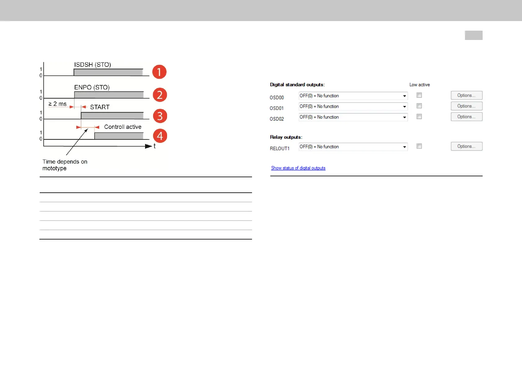
Fig. 9.4: Time diagram of sequences
Command System state
①
Startinglockout ISDSHSafeStandstill(STO)
②
Readyforstart ENPOEnablePower
③
On Bit(0)=START(1)
④
Activecontrol Activecontrol
Legend to Time diagram of sequences
MOOG
ID
No.: CB40859-001 Date: 02/2018
MSD Servo Drive- Device Help
238
9 Input/Output settings
9.3Digitaloutputs
Fig. 9.5: “Function selection of digital outputs” screen
9.3.1Standarddigitaloutputs
Thereisaselectorthatcanbeusedtoassignafunctiontoeachdigital
standardoutput.
Certainfunctionswillonlybeavailablewithspecificfunctionpackages.
Dependingontheconfiguredfunction,the“Options...”buttonmaybecome
enabled.Ifitis,thisbuttoncanbeusedtoswitchtoadifferentscreendirectly
anddefinethefunction’sexactbehaviourthere.
Allstandardoutputscanbeswitchedfrom“active-high”to“active-low”(bits1
to3inP 142[0] - MPRO_OUTPUT_INV).
Digital input states
Clicking on the “Status of digital outputs” field on the input screen for the digital
outputs will open a visualization showing the digital outputs’ states (see
Section "Status of digital outputs" on page 241).
9.2.8Pulse-Direction
From firmware 124.20-08 additional document
CC41778-001 applies

 Loading...