6.6Channel2:InterfaceX6
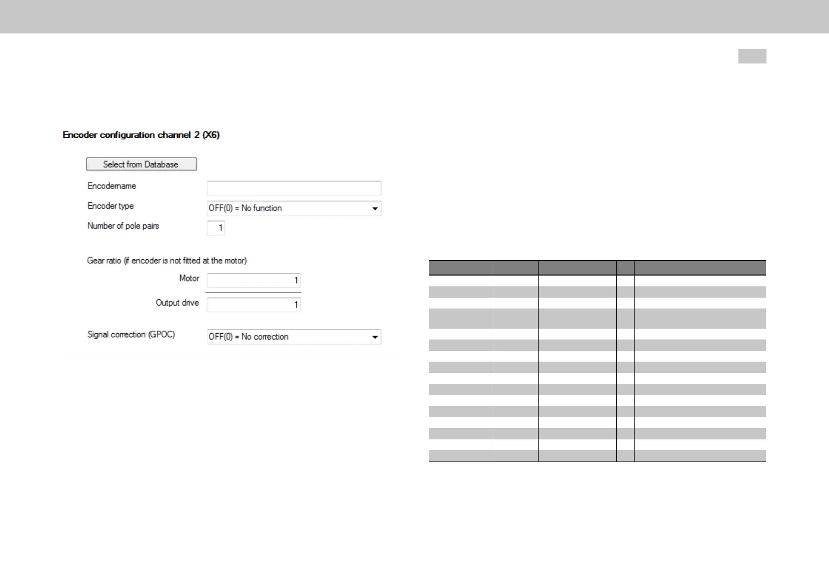
Fig. 6.3: Encoder configuration channel 2 (X6) screen
This screen is used to select the encoder for channel Ch2. This channel is used to
measure position changes periodically and add them up cyclically – what is referred
to as “cyclical evaluation”. Encoder channel Ch2 does not feature an absolute value
interface. In addition to evaluating resolvers, this channel can also be used to
acquire “simple” Sin/Cos signals (up to a maximum of 1 kHz and with no zero pulse).
Resolvers must always be evaluated using encoder channel Ch2 (P506 - ENC_
CH2_Sel = RES(1)). The resolver pole pairs are set via P560[0] - ENC_CH2_Lines.
MOOG
ID
No.: CB40859-001 Date: 02/2018
MSD Servo Drive- Device Help
70
6 Encoder
Resolver basics and requirements
The connected resolver must meet the following criteria:
Ccw(positivesignalprogresscorrespondstoananticlockwisedirection
whenlookingattheshaftfromabove)
Notransformationphaseshift
Transformationratioofapprox.0.5
GPOC is a special Moog real-time process that is used to improve the quality of Sin/
Cos signals before they are used to calculate a position. If Sel = RES(1) or Sel =
SINCOS(2), this process may come in handy. For details see Section
"Signal correction GPOC (Gain Phase Offset Correction)" on page 71.
Table 6.15: Encoder configuration channel 2 (X6) parameters
P No. Index Name / Settings Unit Description
506 0 ENC_CH2_Sel
OFF(0)
RES(1)
SinCos(2)
512 0
513 0
560 0
561 0
562
0
1
2
3
4
563 0
564 0
ENC_CH2_Num
ENC_CH2_Denom
ENC_CH2_Lines
ENC_CH2_Corr
ENC_CH2_CorrVal
OffsetB
OffsetA
GainB
GainA
Phase
ENC_CH2_EncObsMin
ENC_CH2_Info
Interfaceconfiguration
Noevaluation
Resolverevaluation
Resolverexcitationshut-off;evaluationof
aSin/Cosencoder(max1kHz)possible.
Numeratorofencodergearing[-1...+1]
Denominatorofencodergearing[only+1]
Numberofpolepairsofresolver
EncodercorrectionGPOC
Signalcorrectionsettings
Offset,TrackBCosinus
Offset,TrackASinus
Gain,TrackB-Cosinus
Gain,TrackA-Sinus
Phasedifference
AmplitudemonitoringMinimum
Encodername

 Loading...