MOOG
ID
No.: CB40859-001 Date: 02/2018
MSD Servo Drive- Device Help
132
7 Control
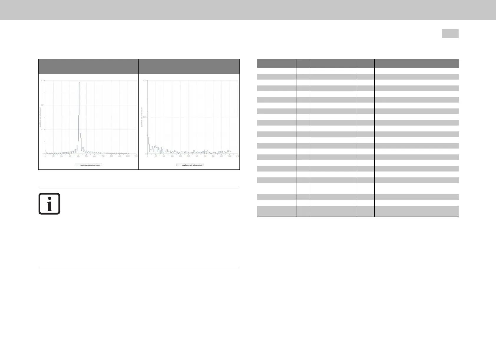
FFT without filtering FFT with filtering
Table 7.14: FFT transformation
NOTE
Notethatthefiltersnotonlyhaveaneffectontheamountbutalso
onthephaseofthefrequencyresponse.Atlowerfrequencies
higher-orderfilters(PT3,PT4)shouldnotbeused,asthephase
withinthecontrolbandwidthisnegativelyinfluenced.
ThecoefficientscanalsobespecifieddirectlyviaparameterP 327
- CON_SCON_FilterPara.Theytakeeffectdirectly,sochanging
themisonlyrecommendedwhenthecontrolisswitchedoff.
Alargebandwidthwillresultinalowerattenuationofthecut-off
frequency.
ID Index Name Unit Description
325
325 0 Hz
325 1 Hz
325 2 Hz
325 3 Hz
326 0
327
CON_SCON_FilterFreq
CON_SCON_FilterFreq
CON_SCON_FilterFreq
CON_SCON_FilterFreq
CON_SCON_FilterFreq
CON_SCON_FilterAssi
CON_SCON_FilterPara
327 0
Filterfrequenciesofdigitalfilter
1stcenter/cutoff
1stwidth
2ndcenter/cutoff
2ndwidth
Digitalfilterdesignassistant
Coefficientsofdigitalfilter
b0*x(k)
327 1
327 2
327 3
327 4
327 5
327 6
327 7
327 8
FilterParab0
FilterParab1
FilterParab2
FilterParab3
FilterParab4
FilterParaa1
FilterParaa2
FilterParaa3
FilterParaa4
b1*x(k-1)
b2*x(k-2)
b3*x(k-3)
b4*x(k-4)
a1*y(k-1)
a2*y(k-2)
a3*y(k-3)
a4*y(k-4)
1550 0
1551 0
1552
1552 0 Hz
1552 1
SCD_NotchType
SCD_NotchCntl
SCD_NotchFreq
SCD_NotchFreq
SCD_NotchLambda Hz/min^-
2
AdaptiveNotchfilter:Method
AdaptiveNotchfilter:Controlword
AdaptiveNotchfilter:Frequencies
AdaptiveNotchfilter:Frequency
AdaptiveNotchfilter:Coefficient
1552 2 Hz
1552 3 Hz
1552 4
SCD_NotchMinFreq
SCD_NotchMaxFreq
SCD_NotchDeltaFreq Hz
AdaptiveNotchfilter:Min.frequency
AdaptiveNotchfilter:Max.frequency
AdaptiveNotchfilter:Maximumfrequency
change(ineachiteration)
Table 7.15: “Speed controller - Digital filter” parameter
7.4.3AnalysisofSpeedcontrol
The speed controller is executed as a PI controller. The gain (P-component) and the
integral-action time (I-component) of the individual controllers are programmable.
In order to optimize the speed control loop, two rectangular reference steps are
preset. For automatic controller optimization the step response and transfer function
wizards are available.

 Loading...