8.11.4Masterconfiguration
Fig. 8.72: “Master configuration” screen
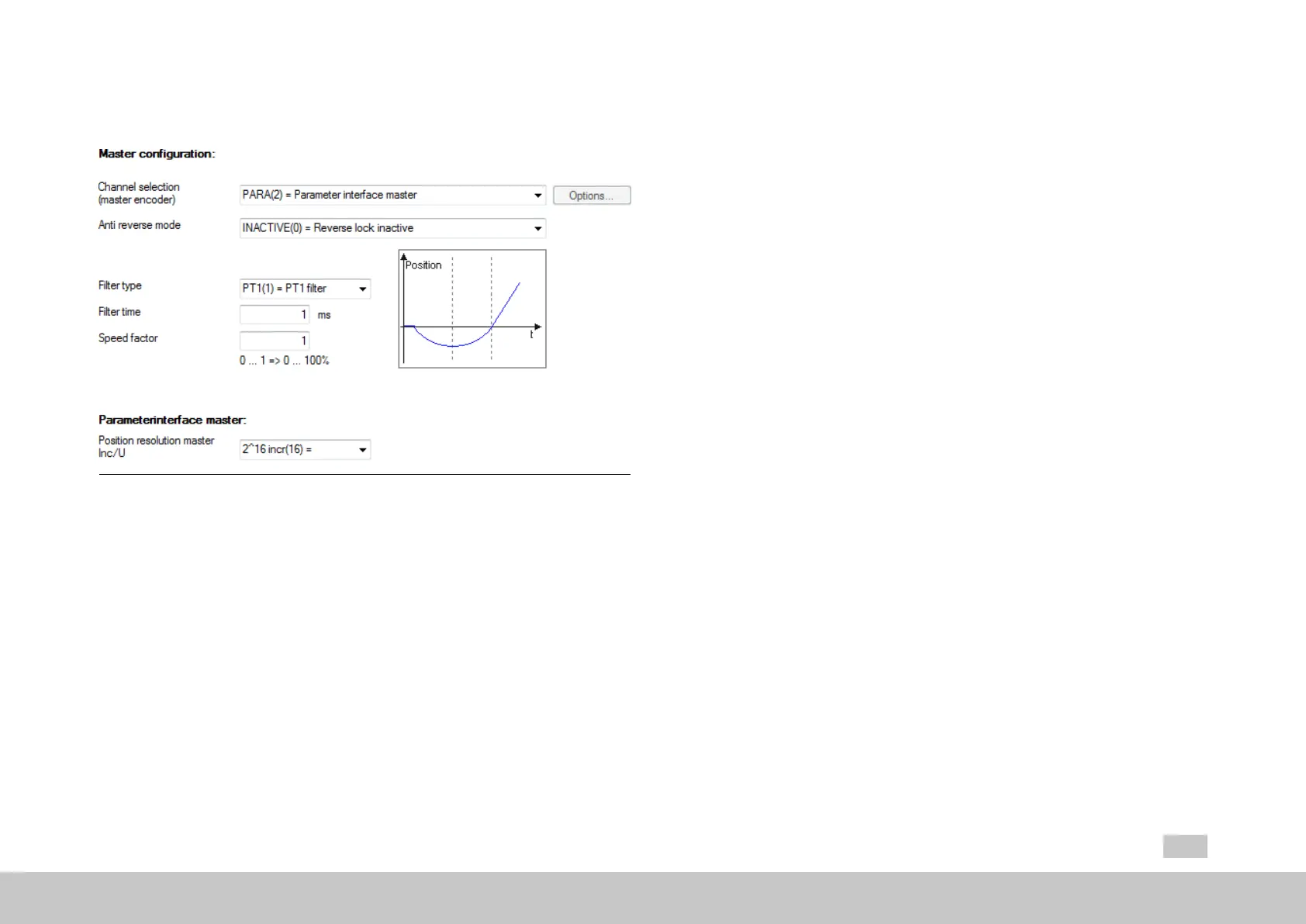
Channel selection (master encoder)
P1319[0] - MPRO_ECAM_CamMaster_AxisType is used to define the master
encoder.
NO AXIS (0) = No axis
VIRTUAL MASTER (1) = Virtual master
Ifyouselectthisfunction,youwillbeabletoconfigureadditionalsettingsby
clickingontheenabled“Options...”button(see Section"Virtualmaster" on
page222).
PARA (2) = Master parameter interface
Ifyouselectthisfunctionbecauseahigher-levelcontrollerisbeingusedas
MOOG
ID
No.: CB40859-001 Date: 02/2018
MSD Servo Drive- Device Help
222
8 Motion profile
themasterencoder,youwillneedtosettheresolutionrelativetoasingle
motorrevolutioninP 250 - MPRO_ECAM_PARAMaster_Amplitude(see
below).
ENC CH1 (3) = Encoder channel 1 X7 (Sin/Cos)
ENC CH2 (4) = Encoder channel 2 X6 (resolver)
ENC CH3 (5) = Encoder channel 3 X8 (optional)
ThisfunctionwillonlybeavailableifthereisanX8externalinterface
(optionalmodule)available.
TP0 (6) = Pulse counter on probe channel 0 (TP0)
TP1 (7) = Pulse counter on probe channel 1 (TP1)
ENC_CH4 (8) = Encoder channel 4 (e.g. fieldbus)
TWIN_POS (9) = TWIN remote reference position (P-2607)

 Loading...