MOOG
ID
No.: CB40859-001 Date: 02/2018
MSD Servo Drive- Device Help
125
7 Control
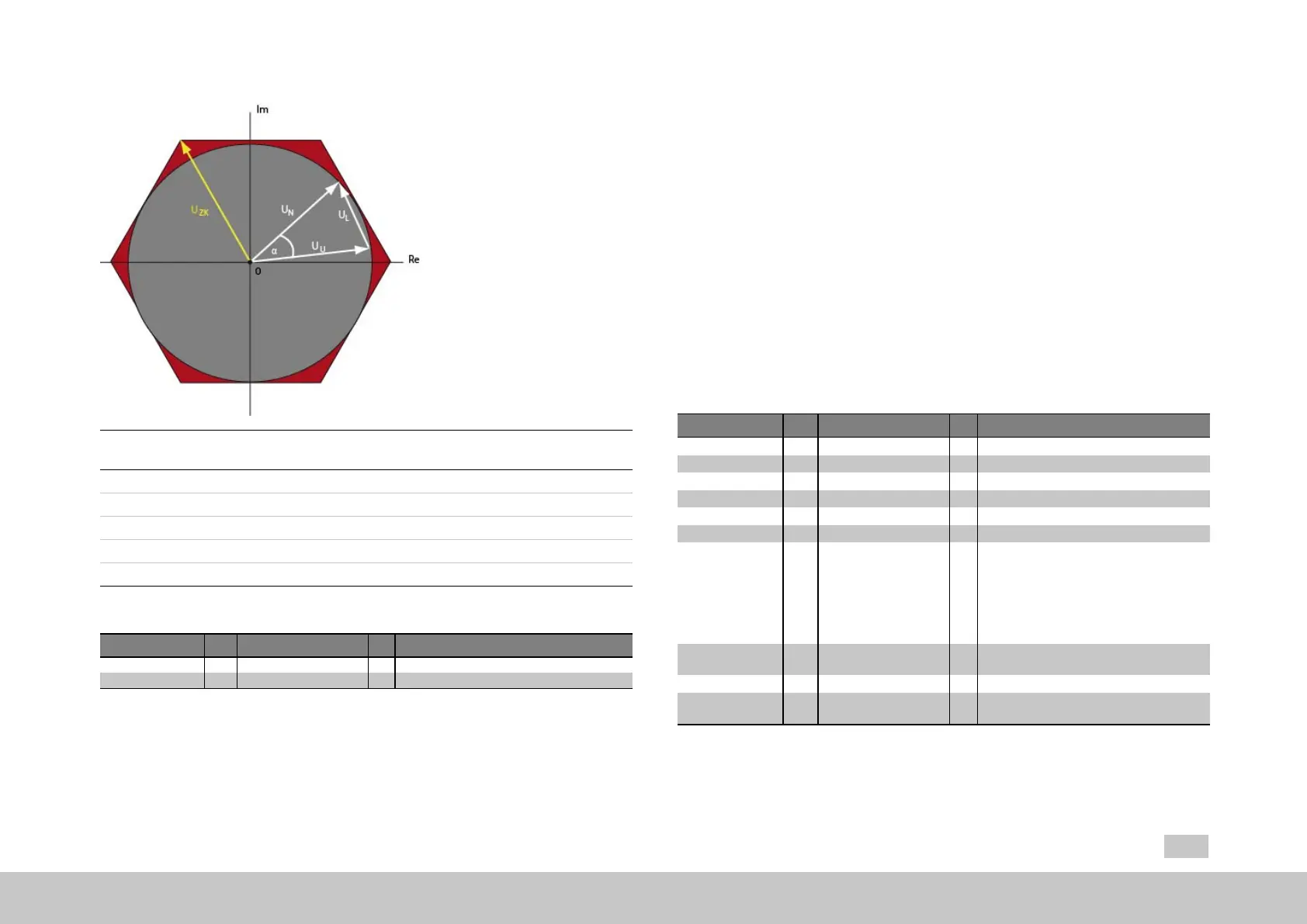
Fig. 7.18: “Circle and hexagon voltages” diagram
U
N
Mainsvoltage
U
l
Voltageatinductor
U
u
Invertervoltage
U
zk
DClinkvoltage
α Phase angle
Legend for “Circle and hexagon voltages” diagram
ID Index Name Unit Description
431 0 CON_CCON_VLimit %
432 0 CON_CCON_Mode
Voltagelimitforfirstcurrentcontroller
Selectcurrentcontrol/limitationmode
Table 7.8: “Advanced torque control - Overmodulation” parameters
7.3.6Torquecontrolwithdefinedbandwidth
The controller gain is determined by activating test signals (Autotuning). The
calculations and the relevant autotuning are carried out in the drive controller. The
advanced settings are made in P1530[0] - SCD_SetMotorControl, P1531[0] -
SCD_Action_Sel and P1533[0] - SCD_AT_Bandwidth.
The3dBbandwidthoftheclosedloopisspecifiedasthebandwidth.
Advisablebandwidthsettingsat8kHzswitchingfrequencyareupto
approximately2000Hz;at16kHzswitchingfrequencyuptoapproximately
3000Hz.
TheP-gainCCON_Kpiscalculatedaccordingtotheamountoptimum.
Theintegral-actiontimeCCON_Tnisinterpolatedbetweentheamount
optimumandthesymmetricaloptimum,sothattheI-contentissufficient,
resultinginreducedinterferenceresponse.
P no. Index Name / Setting Unit Function
1530 0 SCD_SetMotorControl
Fault(-1)
Ready(0)
CALC_CON(1)
CALC_ASM(2)
BANDWIDTH(3)
DEADBEAT(4)
Torquecontrollersettingwithdefinedbandwidth
Errorduringcalculation
Calculationready
Controlwithmotordatacalculation
Calculateasmmotorfromrateddata
Calculatecurrentcontrollerbybandwidth
Thissettingparameterizesadead-beat
controller.Thestructureisswitchedto
feedbackwithobserver,theobserveris
designed(toaspecificequivalenttimeconstant
–forsettingseeP 434[0] - CON_CCON_
ObsPara–andthespeedcontrollergainsare
calculatedaccordingly.
1531 0 SCD_Action_Sel Startconditionstodeterminethetorque
controllersettings
FAULT(-1) Selectedfunctionstoppedwithfault
READY(0) Readytostartfunction/lastcallsuccessfully
ended
Table 7.9: “Torque control with defined bandwidth” parameters

 Loading...