MOOG
ID
No.: CB40859-001 Date: 02/2018
MSD Servo Drive- Device Help
124
7 Control
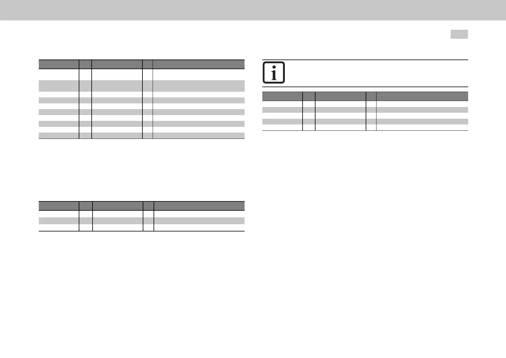
ID Index Name Unit Description
471 0 MOT_Lsig mH
472 MOT_LsigDiff
472 0 Lsig_q@I0 %
Motorleakageinductance(ASM)/stator
inductance(PSM)
q-axisstatorinductancevariation(relativeto
MOT_Lsig)
Inductance@CurrentI0
472 1 Lsig_q@I1 %
472 2 Lsig_q@I2 %
472 3 Lsig_q@I3 %
Inductance@CurrentI1
Inductance@CurrentI2
Inductance@CurrentI3
472 4 CurrentI0 %
472 5 CurrentI1 %
472 6 CurrentI2 %
472 7 CurrentI3 %
CurrentI0relativetoMOT_CNom
CurrentI1relativetoMOT_CNom
CurrentI2relativetoMOT_CNom
CurrentI3relativetoMOT_CNom
Table 7.5: “Advanced torque control - Saturation characteristic” parameters
7.3.5.1.2K-Tcharacteristic
In the overload range the output-side torque is reduced due to rising losses
(iron/copper losses). This behaviour can be compensated by P479[0] - MOT_
TorqueSat.
P No. Index Parameter name Unit Function
479 MOT_TorqueSat
0to4 Nm
5to9 A
Motortorqueasafunctionofthecurrent
Torque;interpolationpoints0to4.
Current;interpolationpoints5to9.
Table 7.6: “K-T characteristic” parameters
7.3.5.2Observer
The speed controller must track a variable moment of inertia in order to adapt the
Servo controller to the machine mechanism (adaptive process). The challenge lies
in precise definition of the moment of inertia, in particular under the influence of
friction, load and other non-modellable disturbances. To nevertheless optimize the
adaptation to the machine mechanism, a technique based on a state observer is
available.
NOTE
PleasecontactMoogbeforeconfiguringtheobserver.
ID Index Name Unit Description
433 0
434
434 0 ms
434 1 1/s
434 2
CON_CCON_ObsMode
CON_CCON_ObsPara
TF
Kp
Tn ms
Selectcurrentobservermode
Currentobserverparameters
Observertimeconstant
Proportionalfeedbackgain
Integralfeedbacktimeconstant
Table 7.7: “Advanced torque control - Observer” parameters
7.3.5.3Overmodulation
The "usqref" and "usdref" components permit so-called overmodulation of the DC
link voltage (limitation to hexagon instead of circle). The maximum output voltage
which can be set for each phase angle results from the circle which fits in the voltage
hexagon (see diagram Section "“Circle and hexagon voltages” diagram" on page
125).
By setting the hexagon modulation "HEX_PHASE(3)", the length of the vector for the
output voltage can be placed in the area of the DC link voltage (red). As a result only
two of the three half-bridges are switched in each switching interval. The third
remains at the upper or lower potential of the DC link voltage for a period of 60° of
the output frequency.
This method has only two thirds of the switching losses of modulation with all three
phases. Disadvantages are higher harmonics of the motor currents and thus less
smooth running at high motor speeds.
Representation of the eight vectors of the three-phase voltage system (3 half-bridges
each with 2 states [2
3
]). The vectors correspond to the DC link voltage U
ZK
and form
a voltage hexagon.

 Loading...