This deviation will be passed on to the process controller. This controller is
implemented as a PI controller with output limiting and an anti-windup function.
Users can set a Kp gain with P2659[0] - CON_PRC_KP, Kp scaling with P2660[0] -
CON_PRC_KPSCALE and a reset time with P2661[0] - CON_PRC_TN. If the
integral-action time is set to the maximum parameter value, the I-component of the
controller is inactive. (CON_PRC_TN = 10000 [ms]).
Moreover, an offset can be added to the signal at the controller’s output by using
P2662[0] - CON_PRC_REFOFFSET. After this, the totalled manipulated variable
will be passed through a limiter. The user can parameterize the limitation via
parameter P2663[0] - CON_PRC_LIMPOS for the positive limit and P2664[0] -
CON_PRC_LIMNEG for the negative limit.
Downstream of the control variable limiter there is another limitation which limits the
changes to the control variable per sampling segment. By way of field parameter
P2680 - CON_PRC_RateLimiter the limitation of the control variable steepness per
millisecond can be parameterized. Subindex 0 is for the limiting used for standard
process controller operation and subindex 1 is for reducing the process controller’s
integral term. For details on how to set the rate limiting, see Section "Rate limiter" on
page 157.
7.10.2.5Manipulatedvariable
The process controller’s manipulated variable downstream of the rate limiter (P2676
[0] - CON_PRC_OUTVAL) can be mapped to various internal drive setpoint or feed-
forward control values. The selection is made via P2672[0] - CON_PRC_OUTSEL.
MOOG
ID
No.: CB40859-001 Date: 02/2018
MSD Servo Drive- Device Help
157
7 Control
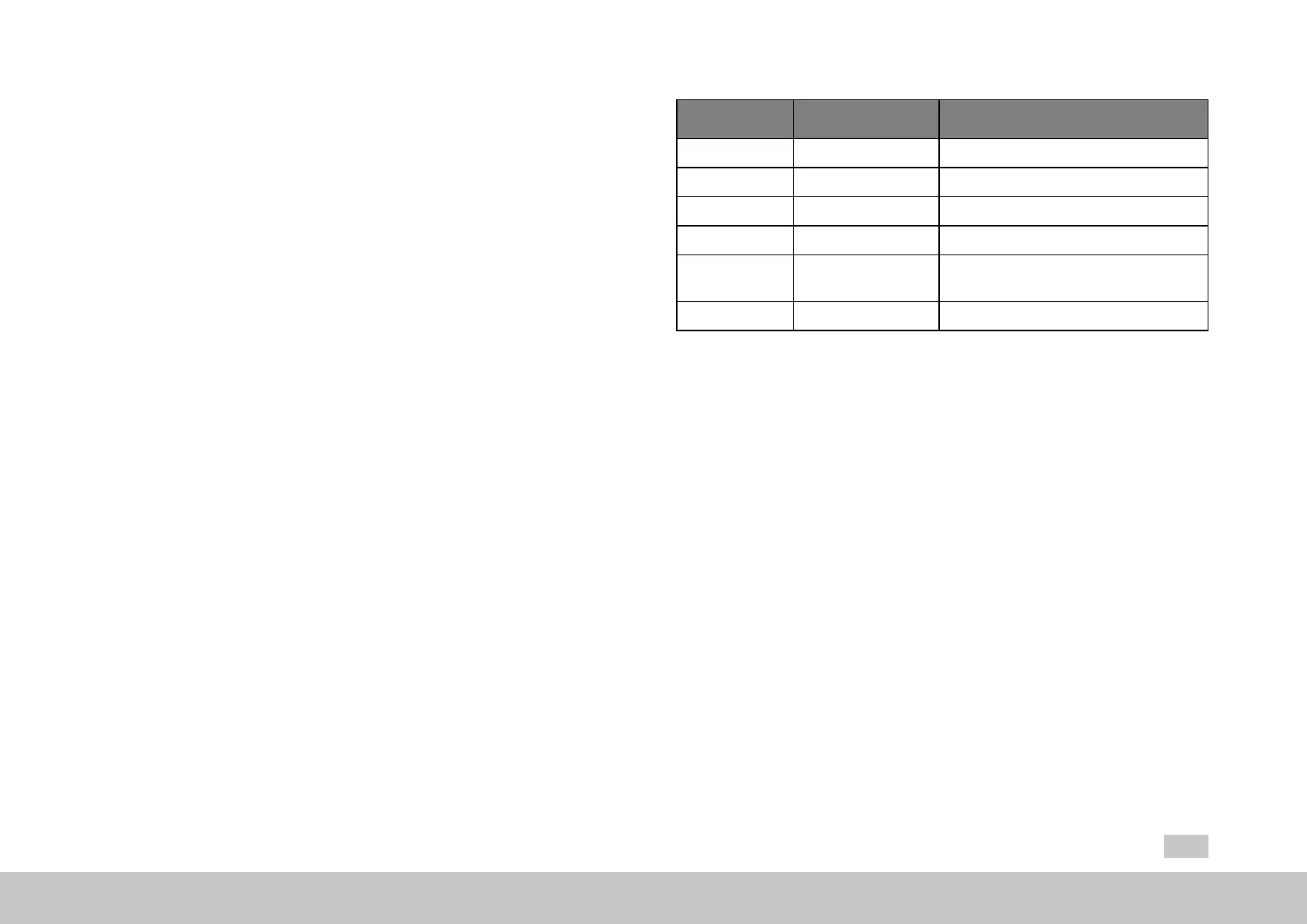
Setting Name Description
0 OFF Nointerventionpoint
1 REFTORQUE Additivetorquereference
2 REFVEL Additivespeedreferencevalue
3 REFPOS Additivepositionreference
4 MPPRO
ReferencevalueforMotionProfilevia
P 2678[0] - CON_OUTSEL_MOPRO
5 REFVEL_RAMP Additivespeedsetpointonramp
Table 7.36: Selector for mapping manipulated variable P 2676[0]
If the additive setpoints are selected (1–3 and 5), it is important to make sure that
they will be fed to the relevant point in the control structure using internal units (see
the “Process controller diagram” figure).
The conversion details for converting internal units to user-specific units must be
gathered from the configured user units. These user units can be found under
“Motion Profile --> Standardization/Units” in the operating tool. It may be possible to
track the conversion between user units and user-specific units depending on
whether the user units have been set up as per CiA 402, SERCOS, or with a user-
specific format. P283[0] - MPRO_FG_Type can be used to view which setup
method was used.
7.10.3Ratelimiter
Downstream of the control variable limiter there is another limitation which limits the
changes to the control variable per sampling segment. By P 2680[0] - CON_PRC_
Rate Limiter the limitation of the control variable steepness per millisecond can be
parameterized. By way of index (0) the limitation is active in standard process

 Loading...