7.9V/Hzmode
A simple function test can be carried out in V/f mode. This test will show users
whether a motor is connected correctly and whether the right direction of movement
will be followed. If ...
Thedirectionofmovementisthewrongone,
Themotorisatastandstill,
Uncontrollablemotionoccurs,
then the connection and the motor data need to be checked.
For testing purposes, a V/f control system is implemented in such a way that the
closed-loop speed control circuit will be replaced by the V/f control. The reference is
the speed reference; the actual speed is set equal to the reference. A linear
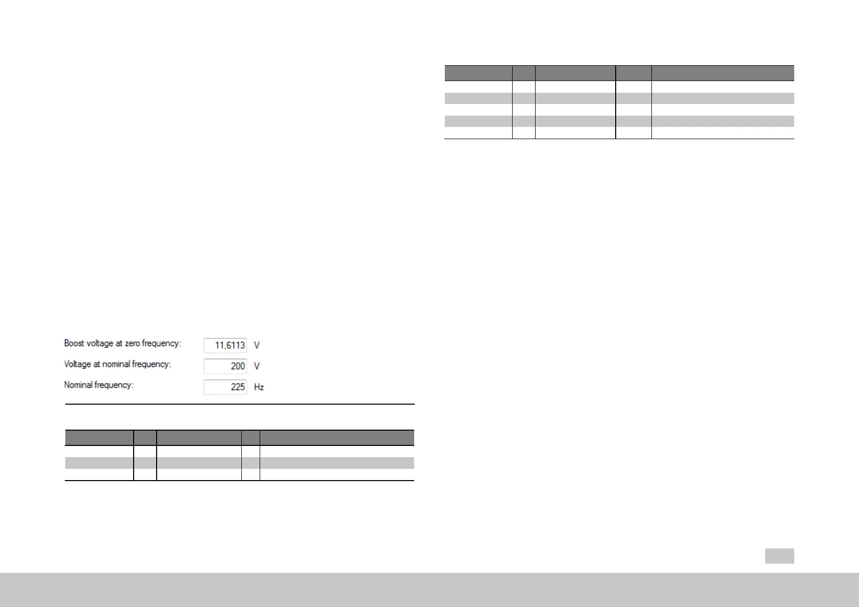
characteristic with two nodes has been implemented, with a fixed boost voltage
setting P313[0] - CON_VFC_VBoost at 0 Hertz. Starting from the rated frequency
P314[0] - CON_VFC_FNom, the output voltage will remain constant at P315[0] -
CON_VFC_VNom. This means that an asynchronous motor will automatically be
driven to field weakening as the frequency rises.
Fig. 7.40: “V/f mode” dialog box
ID Index Name Unit Description
313 0 CON_VFC_VBoost V V/fcharacteristic:Boostvoltage
314 0 CON_VFC_FNom Hz V/fcharacteristic:Ratedfrequency
315 0 CON_VFC_VNom V V/fcharacteristic:Nominalvoltage
Table 7.30: “V/f mode” parameters
MOOG
ID
No.: CB40859-001 Date: 02/2018
MSD Servo Drive- Device Help
153
7 Control
ID Index Name Unit Description
19 0 epsRS Polewidth Rotor/statorelectricalangle
20 0 freqRS Hz Rotor/statorelectricalfrequency
21 0 freqFS Hz Field/statorelectricalfrequency
29 0 vmot V Currentmotorvoltage
312 0 CON_CCON_VMot V Currentmotorvoltage(rms,phase-to-phase)
Table 7.31: Scope signals “V/Hz mode (basic)”

 Loading...