Usage examples
Changetoinputvoltagerangeofanalogtorquescaling
Changetoinputvoltagerangeofspeedoverridefunction
Changetoswitchingthresholdofadigitalinputfunction
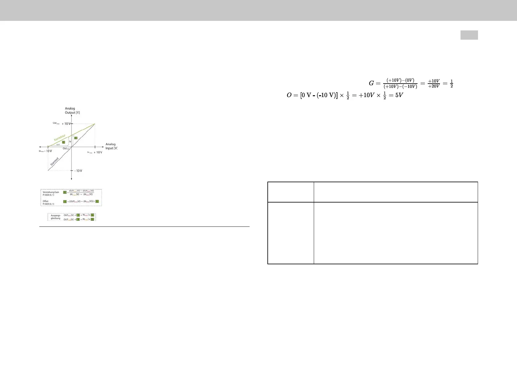
Fig. 9.9: Scaling of an analog channel
Example: Analog torque scaling
The standard setting for the drive is an input voltage range of 0 V to +10 V,
corresponding to 0 % to 100 %. With this setting, any value between -10 V and 0 V
corresponds to 0 %.
Saythatyouwantaninputvoltagerangeof-10Vto+10V,inwhichcase-10
Vwouldcorrespondto0%ofthetorqueand+10Vto100%ofthetorque.
o
In
min
=-10V,Out
min
=0V
MOOG
ID
No.: CB40859-001 Date: 02/2018
MSD Servo Drive- Device Help
246
9 Input/Output settings
o
In
max
=+10V,OUT
max
=+10V
Thecorrespondingformulasare: and
ResultinginagainofG=0.5andanoffsetofO=5V
9.4.4Profilemodeandanaloginputs
Parameter P301[0] - CON_REF_Mode determines whether the reference values
are processed via the profile generator (setting “PG(0)”) or directly (setting “IP(1)”). If
direct input via IP mode is selected, only the input filters are active. The analog
values are scanned and filtered in the torque control cycle and then directly
transferred as references for the speed or torque control.
CAUTION! Your system/motor may be damaged if put into operation in
an uncontrolled or inadequate manner.
Failure to exercise caution or follow proper working
procedures may result in damage to your system/motor.
Beforethe“Start”step,makeabsolutelysurethatavalid
setpointhasbeenentered,astheconfiguredsetpoint
willbeimmediatelytransmittedtothemotorafterthe
motorcontrolfunctionstarts,whichmayresultinthe
motoracceleratingunexpectedly.

 Loading...