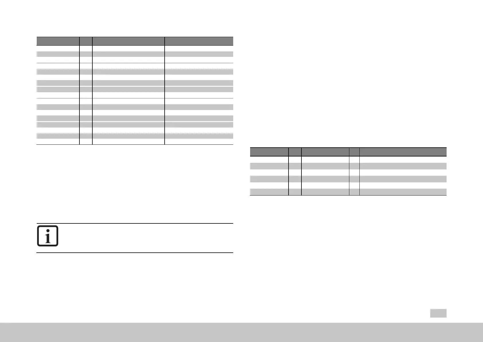
ID Value Name
576 ENC_CH3_Mode
0000h Data_EncObs Default:withwirebreak
0001h Data_Nothing
0002h Data_POdd_EncObs ODDParity
0003h Data_Free_POdd_EncObs
0004h Data_POdd
0005h Data_Free_POdd
0006h Data_Free_EncObs
0007h Data_Free_Free_EncObs
000Ch Data_PEven_EncObs EVENParity
000Dh Data_Free_PEven_EncObs
000Eh Data_PEven
000Fh Data_Free_PEven
001Fh Data_Free Extradatareading
0020h Data_Free_Free
0021h Data_Free_Free_Free
0022h Data_Free_Free_Free_Free
Table 6.26: SSI mode parameters (all other values are reserved)
P636[0] - ENC_CH3_CycleCount◂ = Sampling cycle in nx125µs (microseconds):
ENC_CH3_CycleCount can be used to slow down the timing for the cyclical SSI
encoder evaluation. By default, ENC_CH3_CycleCount = 1, i.e. the default setting
corresponds to 125µs sampling and cycles for the encoder evaluation. Different
settings must be viewed as special cases and must only be used when necessary.
6.7.7Encodergearing
NOTE
Pleasereadthegeneralinformationonencodergearingfoundin
Section"Introduction"onpage50beforehand.
Encoder channels Ch1 to Ch3 each feature their own encoder gearing, while
encoder channel Ch4 (virtual encoders) does not feature
any
encoder gearing.
MOOG
ID
No.: CB40859-001 Date: 02/2018
MSD Servo Drive- Device Help
87
6 Encoder
In the case of encoder channel Ch2, it is assumed that the resolver will always be
used as a commutation encoder on the motor shaft. Because of this, the numerator
adjustment range is limited to a value of (+1) or (-1), while the denominator is set at a
fixed value of (+1), for the Ch2 encoder gearing ratio. This means that the only
option available is to invert the encoder signal (direction reversal).
As a whole, the encoder gearing is a scaling factor in the encoder evaluation system
and consists of numerator N (ENC_CHx_Num) for the motor side and denominator D
(ENC_CHx_Denom) for the encoder side (output side).
The following are used to configure the encoder gearing...
Ch1withP 510[0] - ENC_CH1_NumandP 511[0] - ENC_CH1_Denom,
Ch2withP 512[0] - ENC_CH2_NumandP 513[0] - ENC_CH2_Denom,
Ch3withP 514[0] - ENC_CH3_NumandP 515[0] - ENC_CH3_Denom,
P No. Index Name Unit Description
510 0 ENC_CH1_Num Denominatorofchannel1
511 0 ENC_CH1_Denom Numeratorofchannel1
512 0 ENC_CH2_Num Denominatorofchannel2
513 0 ENC_CH2_Denom Numeratorofchannel2
514 0 ENC_CH3_Num Denominatorofchannel3
515 0 ENC_CH3_Denom Numeratorofchannel3
Table 6.27: Parameters for encoder gearing
Parameters
P 500[0] - ENC_CH1_ActVal[0].SingleTurnand
P 500[1] - ENC_CH1_ActVal[1].MultiTurn
are used, for example, to indicate the current position value at the output for encoder
channel Ch1. These parameters can also be used for checking purposes during
commissioning.

 Loading...