9Input/Outputsettings
Chapter overview
Pictogram
Navigation ►Projecttree►DriveSettings►I/Oconfiguration
Brief description Thischapterdescribeshowthedigitalinputsandoutputs,the
analoginputsandoutputs,andthemotorbrakeoutputonthe
MSDServoDriveandMSDSingle-AxisServoDriveCompact
workandareconfigured.
Contents
9.1 Input/Output settings
231
9.2 Digital Inputs
232
9.3 Digital outputs
238
9.4 Analog inputs
243
9.5 Analog outputs (option for MSD Servo Drive only)
9.6 Motor brake output
248
MOOG
ID
No.: CB40859-001 Date: 02/2018
MSD Servo Drive- Device Help
231
9 Input/Output settings
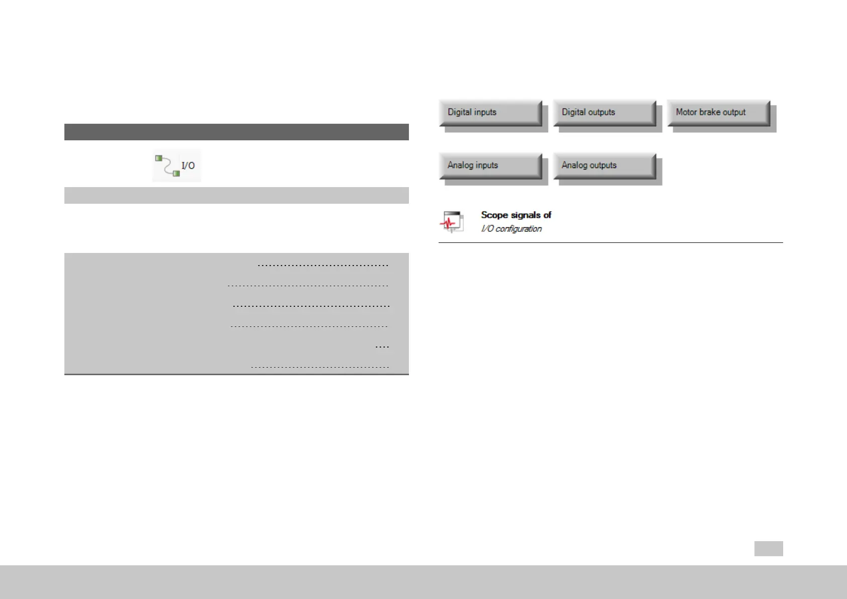
9.1Input/Outputsettings
Fig. 9.1: “Inputs/Outputs settings” dialog box
The buttons on this screen can be used to access and configure the individual input
and output types.
Inputs
Beforeusingthedigitalinputs,theyarenormallyassociatedwithaspecial
devicefunctionalityfordigitalinputswiththeuseoffunctionselectors.
Likewise,beforeusingtheanaloginputs,thesearenormallyassociatedwith
aspecialdevicefunctionalityforanaloginputs.Thecorrespondingfunction
selectorsalsomakeitpossibletoselectaspecialdigitalfunctionalityinstead.
Twoofthedigitalstandardinputsonthedevicearewhatarereferredtoas
“touchprobeinputs”.Theseinputsarefasterthantheotherinputs.
247

 Loading...