Other parameters, such as Num and Denom, are described elsewhere (see
Section
"X6 encoder gearing" on page 73).
P 561[0] - ENC_CH2_Corr=Signalcorrectiontype
TheGPOCroutineusedfortracksignalcorrectionpurposesforsine/cosine
signalsisusedtocompensateforsystematicerrors.Theroutineiscontrolled
withtheCorrandCorrValparameters(see Section"Signalcorrection GPOC
(GainPhaseOffsetCorrection)"onpage71).
P 563[0] - ENC_CH2_EncObsMin=Encodermonitoringminimum,sqrt (a²
+b²)
ThisparameterisusedtoscaletheresolverandSin/Coswirebreak
monitoringandrepresents the“downwards threshold”foranerror message.
Thedefaultsettingis0.2,correspondingtoapprox.20%ofthe tracksignals’
amplitude(approx.80%correspondstoapprox.1Vss).If EncObsMinisset
to0,the resolverandSin/Coswirebreakmonitoringwillbe disabled(see
Section"Channel1:InterfaceX7"onpage56 aswell).
MOOG
ID
No.: CB40859-001 Date: 02/2018
MSD Servo Drive- Device Help
71
6 Encoder
When using long resolver cables, there will be a phase difference between the drive
exciter output signal and the drive track input signals (S1-S3 and S2-S4). This phase
difference can be compensated for with P565[0] - ResExc: ResExc is the time, in µs
(microseconds),
by which the resolver excitation will lead. Moreover, P565[1] - Delay
can be used to compensate for a commutation dead time, which can become
important in the case of higher rotating field frequencies. When there is an absolute
reduction in signal strengths (amplitudes) as a result of the long cables, P566[0] -
ENC_CH2_Amplitude can be used to subsequently increase these amplitudes (up to
a maximum of +10.5 %) so that there will be a magnitude level of 80–85 % for track
signals. This is achieved by adjusting the resolver excitation amplitude. Parameter
P567[0] - ENC_CH2_EncObsAct can be used to check the effects of adjusting the
compensation settings. It returns the length of the phasor for track signals (sqrt(a²+b²))
and is accordingly a measure of “the amplitude” of track signals: If the phase shift is
properly corrected at the end of the compensation adjustment process, you can save
the settings.
NOTE
ThisfunctionisnotavailablefortheMSDSingle-AxisServoDrive
Compact.
Donotusecablelengths>50mwithoutfirstconsultingwith
Moog.
6.6.2SignalcorrectionGPOC(GainPhaseOffset
Correction)
The resolver and Sin/Cos incremental encoder demonstrate systematic errors that
are reflected in the measured position and in the speed calculated from this (gain and
phase errors, offset components of the tracking signal). The GPOC method for track
signal correction compensates systematic errors. GPOC is available for encoder
channels 1 and 2.
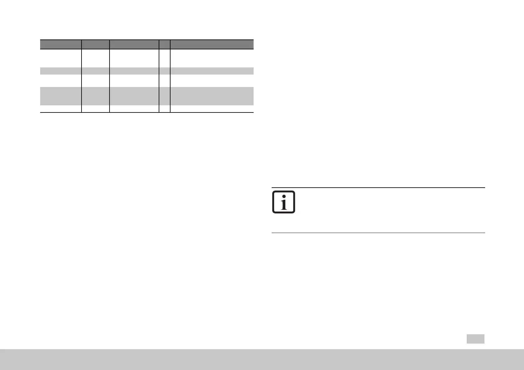
6.6.1Compensationforlongresolvercables
P No. Index Unit Description
565
Name / Settings
ENC_CH2_LineDelay µs Correctionofphaseshiftforcablelengths
>50m(onlyafterconsultationwith
LTIMotion).
0 ResExc us Excitersignalphaseshift
Delay us Compensationforcommutationangle
delay
566 0 ENC_CH2_Amplitude ± Correctionofamplitudeforcablelengths>
50m(onlyafterconsultationwith
LTIMotion).
567 0 ENC_CH2_EncObsAct Amplitudeofanaloguesignal
Table 6.16: Encoder configuration channel 2 (X6) parameters (continue)
The Sel and Lines parameters are self-explanatory.

 Loading...