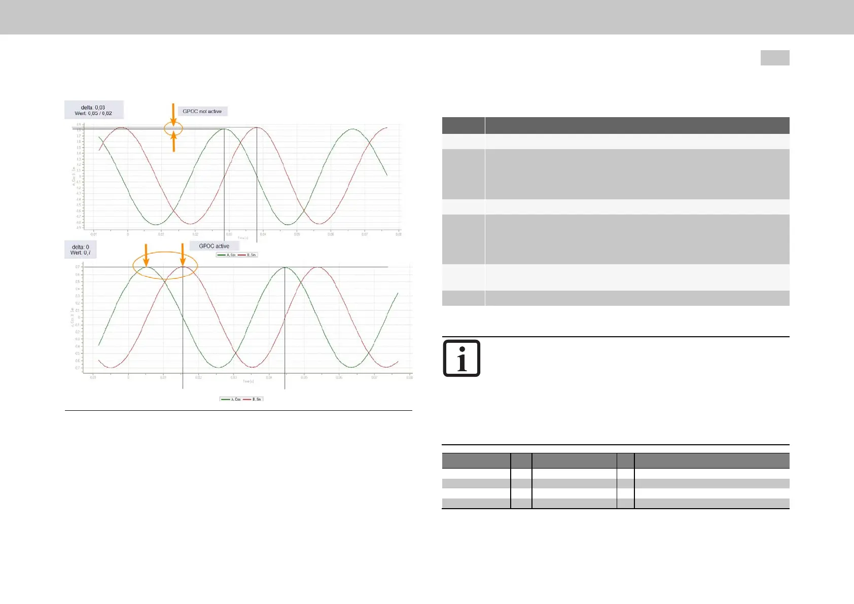
Fig. 6.4: Track signals with and without GPOC
MOOG
ID
No.: CB40859-001 Date: 02/2018
MSD Servo Drive- Device Help
72
6 Encoder
Procedure
Step Action
1. Openthemanualmodewindowandsetspeed-controlledmode.
2.
Motoroperatedatconstantspeed
Resolver:1000rpm
Sin/Cosincrementalencoder:1to5rpm.
3. SetP 549[0] - ENC_CH1_Corrto"ADAPT(2)=Autocorrection"
4.
Waitabout1–3minutes.Duringthistime,thecompensationalgorithms
willreachtheirsteadystate.Speed ripple should decrease after about 1
minute.Thiscanbemonitoredwiththeactualspeedvalue in the scope
orwithP 550 - ENC_CH1_CorrVal.
5.
SetP 549[0] - ENC_CH1_Corrto"CORR(1)=Correctionwithsaved
values".
6. Saveinthedevice
Table 6.16: Configuring and activating GPOC
NOTE
Theroutinecanalsobekeptenabledpermanently.However,this
approachislessrobustandrequirescarefultestingtodetermine
whethertheimprovedencoderevaluationqualitywillactuallybe
maintainedduringcontinuousoperation.
TheGPOCroutinewilldeterminetheparametersindividuallyfor
eachencoder.Ifthemotorisreplaced,theGPOCroutinemustbe
activatedagain.
ID Index Name Unit Description
549 0 ENC_CH1_Corr Signalcorrectiontype
550 ENC_CH1_CorrVal Signalcorrectionvalues
550 0 OffsetA Offset,trackA-cosine
550 1 OffsetB Offset,trackB-sine
Table 6.17: Signal correction (GPOC) parameters for channel 1 (X7)

 Loading...