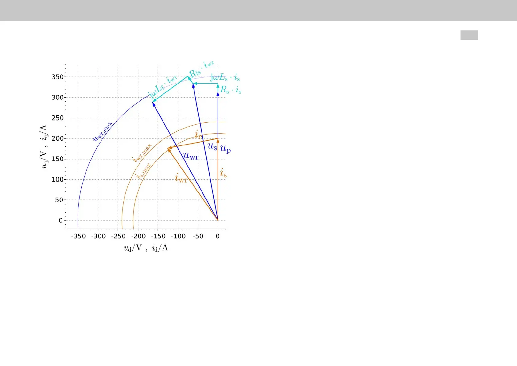
Fig. 5.15: Phasor diagram for a sine wave filter
MOOG
ID
No.: CB40859-001 Date: 02/2018
MSD Servo Drive- Device Help
46
5 Motor
Current
The inverter output current is equal to the sum of the motor current (
i
s
) and capacitor
current (
i
c
). Accordingly, (
i
c
) needs to be taken into account when calculating current
setpoints. Disregarding resistances, the following applies to the capacitor current
components:
i
sd,Cf
= -2•π•
f
S
•
C
f
•
u
sq,mot
i
sq,Cf
= 2•π•
f
S
•
C
f
•
u
sd,mot
Voltage
In this case, the motor voltage for the desired current setpoint vector (
i
sd,ref
,
i
sq,ref
) is
calculated using specified motor parameters
L
S
and Psi_P as a function of stator
frequency (
f
S
):
u
sd,mot
= -2•π•
f
S
•
L
S
•
i
sq,ref
u
sq,mot
= 2•π•
f
S
•(
L
S
•
i
sd,ref
+Psi_P)
Dynamic performance
In addition to the described effect of motor filters on the current phasor in steady-
state operation, there is also an effect on the current control circuit’s dynamic
performance. Among other things, the use of a sine wave filter will result in
resonances.
In order to avoid exciting oscillations, the current control circuit’s decoupling network
is always deactivated when configuring the motor filter support. In addition, the
current controller’s gain may have to be significantly reduced in order to achieve
stability. Because of this, the use of sine wave filters is not recommended for drives
that require a high dynamic performance.

 Loading...