96 KByte Flash Module (S12FTMRG96K1V1)
MC9S12G Family Reference Manual Rev.1.27
1012 NXP Semiconductors
NOTE
User margin levels can be used to check that Flash memory contents have
adequate margin for normal level read operations. If unexpected results are
encountered when checking Flash memory contents at user margin levels, a
potential loss of information has been detected.
28.4.6.13 Set Field Margin Level Command
The Set Field Margin Level command, valid in special modes only, causes the Memory Controller to set
the margin level specified for future read operations of the P-Flash or EEPROM block.
Upon clearing CCIF to launch the Set Field Margin Level command, the Memory Controller will set the
field margin level for the targeted block and then set the CCIF flag.
NOTE
When the EEPROM block is targeted, the EEPROM field margin levels are
applied only to the EEPROM reads. However, when the P-Flash block is
targeted, the P-Flash field margin levels are applied to both P-Flash and
EEPROM reads. It is not possible to apply field margin levels to the P-Flash
block only.
Valid margin level settings for the Set Field Margin Level command are defined in Table 28-58.
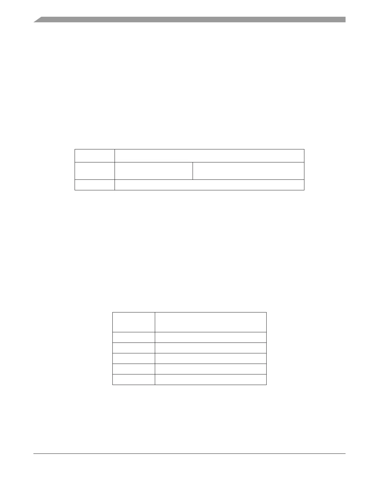
Table 28-57. Set Field Margin Level Command FCCOB Requirements
CCOBIX[2:0] FCCOB Parameters
000 0x0E
Flash block selection code [1:0]
. See
Table 28-34
001 Margin level setting.
Table 28-58. Valid Set Field Margin Level Settings
CCOB
(CCOBIX=001)
Level Description
0x0000 Return to Normal Level
0x0001 User Margin-1 Level
1
1
Read margin to the erased state
0x0002 User Margin-0 Level
2
2
Read margin to the programmed state
0x0003 Field Margin-1 Level
1
0x0004 Field Margin-0 Level
2

 Loading...


