75
F3SG-SR
User’s Manual
Chapter2 Muting
System Operation and Functions
E
Basic wiring diagram
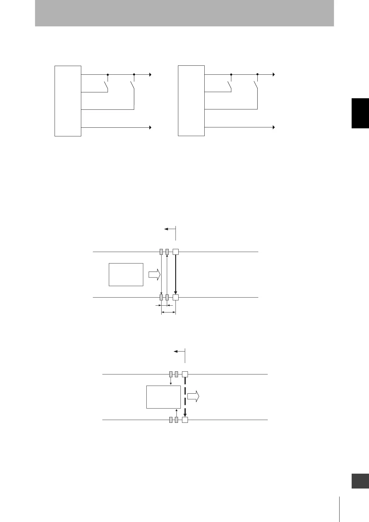
2-13-3-2. Installation Example of Exit-Only Muting Mode
This is an installation example of the Exit-Only Muting mode. When using the Exit-Only Muting mode,
install the muting sensors on the hazardous side of the workpiece exit.
This can be used if a workpiece has a certain length and the hazardous side of the workpiece exit has
enough space around it.
1. Before a workpiece passes through
All muting sensors are turned OFF and the safety function of the F3SG-SR is working.
2. MUTING started
When the muting sensors A1 and B1 are turned ON in this order, and the MUTING state is enabled. In
this state, the safety function of F3SG-SR is disabled.
+24 VDC
0V
PNP
NPN
S1 S2
0V
+24 VDC
S1 S2
24V/0V (Brown)
F3SG-SR
receiver
MUTE B/
COM(-) (Pink)
MUTE A/PRE-RESET/PSDI/COM(+)
(Gray)
0V/24V (Blue)
S1, S2: Muting sensor
F3SG-SR
receiver
24V/0V (Brown)
MUTE B/
COM(-) (Pink)
MUTE A/PRE-RESET/PSDI/COM(+)
(Gray)
0V/24V (Blue)
Workpiece
F3SG-SRA1 B1
Hazardous zone
A1 : Muting sensor to be connected
to muting input A
B1 : Muting sensor to be connected
to muting input B
d1: Distance between A1 and B1
d2: Distance between A1 and F3SG-SR
V
d2
d1
Workpiece
F3SG-SRA1 B1
Hazardous zone
V

 Loading...


