328
Chapter6 Wiring Examples (for F3SG-SR)
F3SG-SR
User’s Manual
Input/Output Circuit and Applications
6-2-2-2. Standard Muting Mode/Exit-Only Muting Mode with Y-Joint Plug
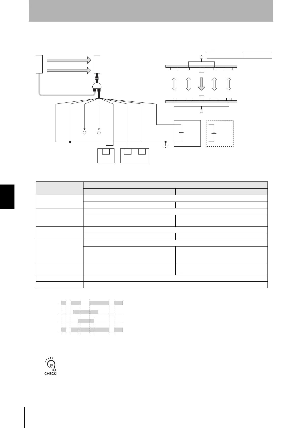
[Wiring Example]
• When using the Y-Joint Plug/Socket Connector (F39-GCNY2), the following functions are not available.
- External Test
- Operating Range Selection by wiring
- Wired Synchronization
•
When a functional earth is necessary, wire an earth cable according to the example in
6-2-1-1.
Auto Reset Mode with
Optical Synchronization and EDM Unused. Also refer to
5-4-4.
Functional Earth Connection for more information.
F39-JGR3K-L and
F39-JG
B-L
F39-GCNY2
24 VDC
Wiring for NPN *1
24 VDC
F39-JGR3K-D and
F39-JG
B-D
24V/0V (Brown)
MUTE B (Pink)
MUTE A (Gray)
0V/24V (Blue)
RESET/EDM
(Yellow)
AUX (Red)
OSSD 1 (Black)
OSSD 2 (White)
*5
IN
PLC *2
IN1
IN2
Emitter Reflector
(E39-R1S)
Reflector
B2B1
Reflector Reflector
A2A1
Receiver
Receiver
Emitter
Safety controller
*3 *4
1
PLC: Programmable logic controller (Used for monitoring only. NOT related to safety system.)
A1, A2, B1, B2: Muting sensor (E3Z-R6)
2
1 2
: Indicates a switch position
Function
Setting
DIP switch SD Manager 3
EDM EDM Disabled (factory default setting)
- [External device monitoring] : Disable *6
Interlock Auto Reset (factory default setting)
- [Start interlock] : Disable
[Restart interlock] : Disable *6
Operating Range
Selection
Long (factory default setting) *7
- [Operating Range Selection] : Long mode *6
Standard Muting Mode
When not using the Intelligent Tap or the SD Manager 3, perform wiring according to the wiring diagram.
N/A [Muting] : Enable
[Muting mode] : Standard Muting (Installation
Example1/2) *6
Exit-Only Muting Mode N/A [Muting] : Enable
[Muting mode] : Exit-Only Muting *6
External Test not used N/A
Optical Synchronization Connect the wires according to the diagram above.
Timing chart
MUTEA
MUTEB
OSSD
Unblocked
Blocked
*1. Reverse the polarity of the power supply when using in the NPN system. Select a PLC
and a safety controller of PNP or NPN type according to the system of your application.
*2. When connecting to the PLC, the output mode must be changed with the SD Manager 3
according to your application. Refer to Chapter 4 Setting with SD Manager 3 for more
information on setting this function by the SD Manager 3.
*3. Refer to 6-3. Connectable Safety Control Units for more information.
*4. The safety controller and the F3SG-SR must share the power supply or be connected to
the common terminal of the power supply.
*5. This is the case for a PELV circuit.
*6. When using the Exit-Only Muting, set the function with the SD Manager 3, restore the
settings to the F3SG-SR, and perform wiring according to the wiring diagram.
*7. To set the Short mode, set the function with the DIP Switches on the Intelligent Tap or
the SD Manager 3, restore the settings to the F3SG-SR, and perform wiring according to
the wiring diagram.
Intelligent Tap Needed *6

 Loading...


