132
Chapter3 Wiring
F3SG-SR
User’s Manual
Setting with Intelligent Tap
3-3. Wiring
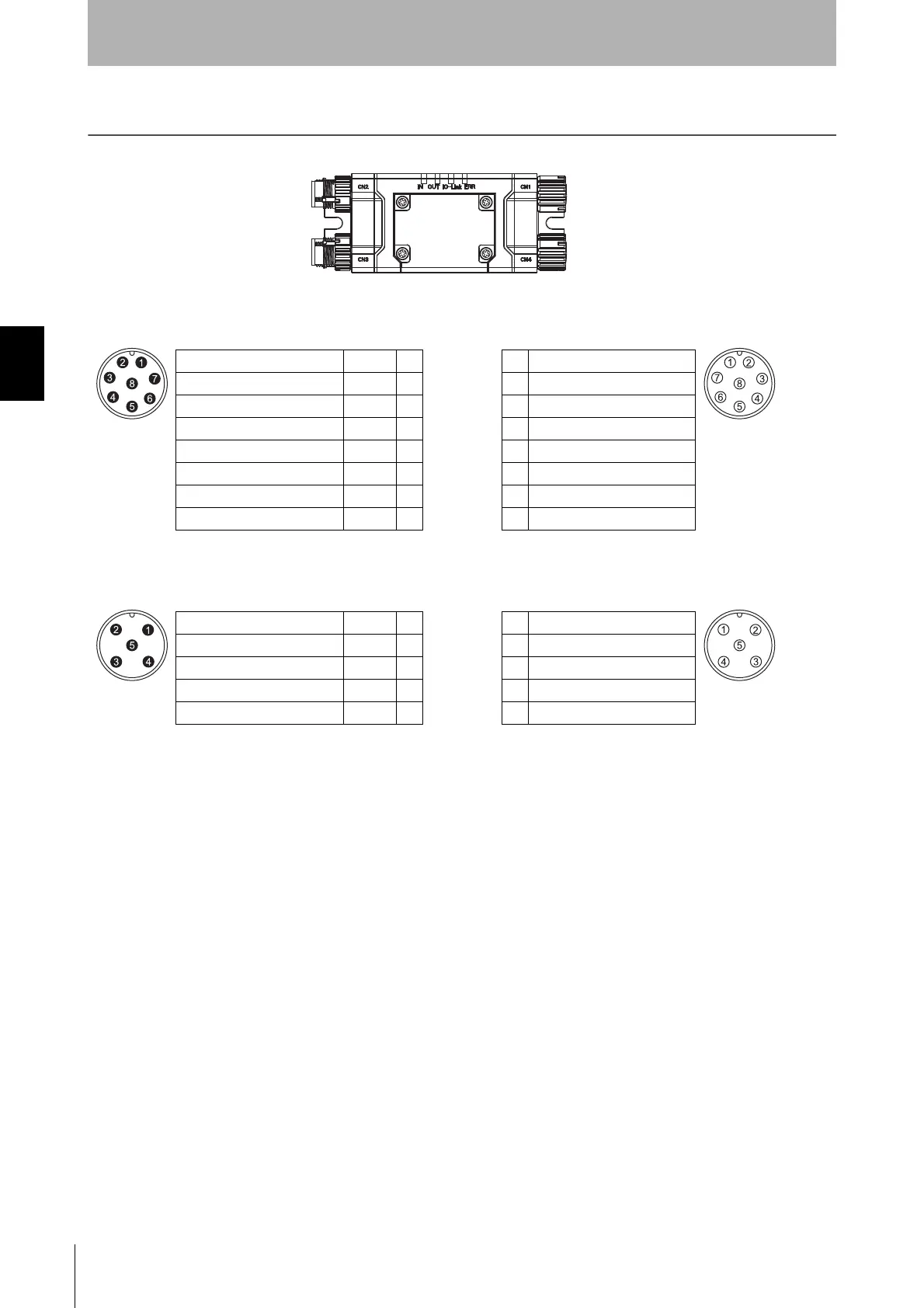
<Internal wiring diagram>
Male
CN2 CN1
Female
RESET/EDM Yellow 1 1 RESET/EDM
24V/0V Brown 2 2 +24V
MUTE A/PRE-RESET/PSDI Gray 3 3 COM(+)
MUTE B Pink 4 4 COM(-)
OSSD 1 Black 5 5 OSSD 1
OSSD 2 White 6 6 OSSD 2
0V/24V Blue 7 7 0V
AUX Red 8 8 AUX
The wire colors are those of the F39-JG
A-D
to be connected to the CN2.
Male
CN3
CN4
Female
L+
Brown 1 1 +24V
DO
White 2 2 TEST
L-
Blue 3 3 0V
C/Q
Black 4 4 COM(+)
Notused
Yellow 5 5 SIO-
The wire colors are those of the XS5F-D521-
DJ0-IL to be connected to the CN3.
CN2
CN3
CN1
CN4

 Loading...


