6-2-2. Muting System Wiring Examples
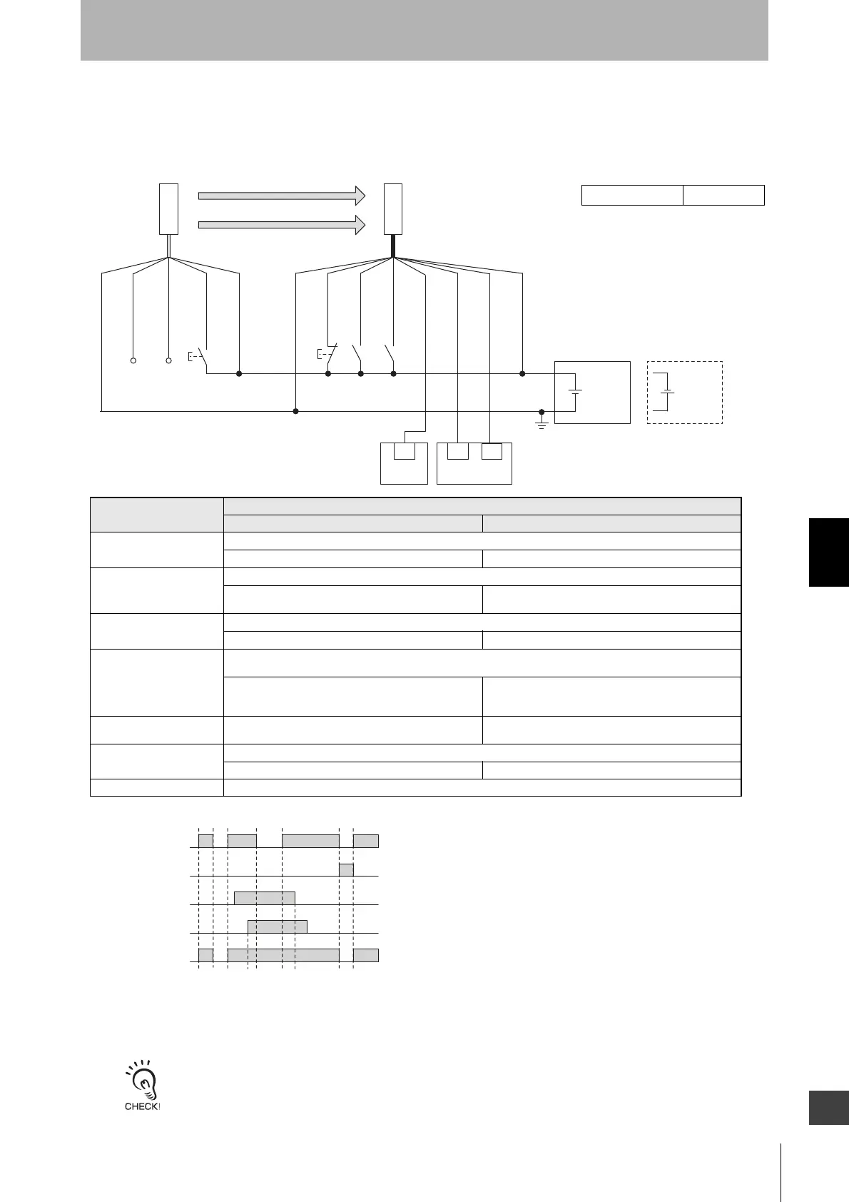
6-2-2-1. Standard Muting Mode/Exit-Only Muting Mode
: Indicates a switch position
Function
Setting
DIP switch SD Manager 3
EDM EDM Disabled (factory default setting)
-
[External device monitoring] : Disable *9
Interlock Auto Reset (factory default setting)
-
[Start interlock] : Disable
[Restart interlock] : Disable *9
Operating Range
Selection
Long : Open the OPERATING RANGE SELECT INPUT line of the emitter or connect the line to 24 VDC.
-
[Operating Range Selection] : Long mode *9
Standard Muting Mode
When not using the Intelligent Tap or the SD Manager 3, perform wiring according to the wiring diagram.
(factory default setting)
N/A [Muting] : Enable
[Muting mode] : Standard Muting (Installation
Example1/2) *9
Exit-Only Muting Mode N/A [Muting] : Enable
[Muting mode] : Exit-Only Muting *9
External Test used Connect the TEST line of the emitter to 24V/0V of the emitter via a test switch (NO contact). *10
N/A [External test signal inversion] : Disable
Optical Synchronization Open the COM(+) and COM(-) lines of the emitter.
*1. Reverse the polarity of the power supply when using in the NPN system. Select
a PLC and a safety controller of PNP or NPN type according to the system of
your application.
*2. Connect the line to 0 VDC if Operating Range Selection is used in Short Mode.
*3. Also used as OVERRIDE INPUT line.
*4. Make sure to connect an override cancel switch to the RESET line when using
the override function. Otherwise the override state may not be released by the
override cancel switch, resulting in serious injury.
*5. When connecting to the PLC, the output mode must be changed with the SD
Manager 3 according to your application. Refer to Chapter 4 Setting with SD
Manager 3 for more information on setting this function by the SD Manager 3.
*6. Refer to 6-3. Connectable Safety Control Units for more information.
*7. The safety controller and the F3SG-SR must share the power supply or be
connected to the common terminal of the power supply.
*8. This is the case for a PELV circuit.
*9. Set the function with the SD Manager 3, restore the settings to the F3SG-SR,
and perform wiring according to the wiring diagram.
*10.This wiring example shows light emission stop when connected to 24 VDC with
PNP setting, and light emission stop when connected to 0 VDC with NPN
setting. If TEST switch is not needed, refer to 2-6. External Test.

 Loading...


