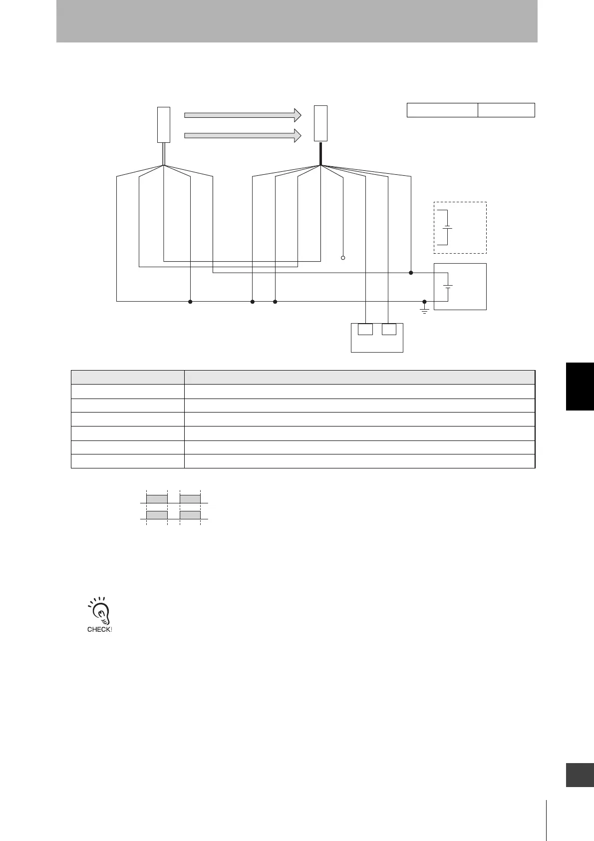
6-2-1-2. Auto Reset Mode with Wired Synchronization and EDM Unused
*1. Reverse the polarity of the power supply when using in the NPN system. Select a safety controller
of PNP or NPN type according to the system of your application.
*2. Refer to 2-6. External Test for more information if External Test is used.
*3. Connect the line to 24V/0V (brown) of the receiver via a lockout reset switch (NC contact) if
Lockout Reset is used.
*4. Refer to 6-3. Connectable Safety Control Units for moreinformation.*6
*5. The safety controller and the F3SG-SR must share the power supply or be connected to the
common terminal of the power supply.
*6. This is the case for a PELV circuit.
*7. The Intelligent Tap is needed to set the Short mode. Set the function with the DIP Switches on the
Intelligent Tap or the SD Manager 3, restore the settings to the F3SG-SR, and perform wi
ring
according to the wiring diagram.
Function Setting
EDM EDM Disabled (factory default setting)
Interlock Auto Reset (factory default setting)
Operating Range Selection Long (factory default setting) *7
Non-Muting system Perform wiring according to the wiring diagram.
External Test not used Connect the TEST line of the emitter to 0V/24V of the emitter.
Optical Synchronization Connect the COM(+) and COM(-) line of the emitter and receiver with each other.
Intelligent Tap Not needed

 Loading...


