276
Chapter5 Mounting
F3SG-SR
User’s Manual
Wiring and Installation
5-3-4. Mounting Procedure
5-3-4-1. Mounting with Side-Mount Brackets (Intermediate Brackets)
(F39-LSGF)
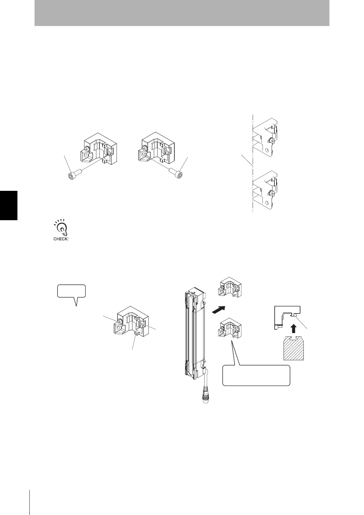
1. Securely tighten the screws to fix the Side-Mount Bracket to the mounting position of the wall surface.
When using more than one Side-Mount Brackets, align them in the same line using the sides of the
brackets that do not face the wall, before attaching the brackets to the sensor. (Fig. 1)
Screws to mount the brackets to the wall are not included.
2. Fully loosen the Mounting Screws (hexagon socket head cap screw (M4×22)). Fit the Brackets (1) and
(2) to the backside of the sensor housing so that the groove of the backside of the housing receives the
hooks of the Brackets (1) and (2). (Fig. 2)
<Backside mounting>
<Side mounting>
Align in the
same line
Fig. 1
M5/M6
M5/M6
Mounting Screw
(hexagon socket head
cap screw (M4×22))
Fit the hooks of Side-Mount
Brackets to the groove of the
backside of the housing
Loosen
Bracket (1)
Bracket (2)
Hoo
Fig. 2

 Loading...


