314
Chapter6 Input/Output Circuit
F3SG-SR
User’s Manual
Input/Output Circuit and Applications
6-1. Input/Output Circuit
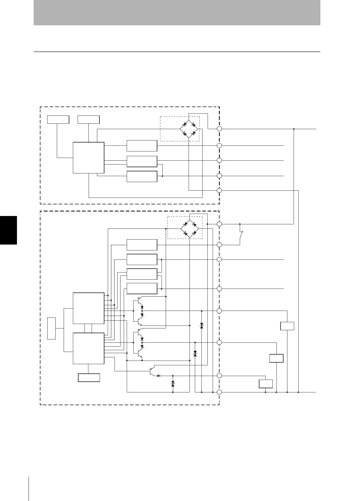
6-1-1. Entire Circuit Diagram
The entire circuit diagrams of the F3SG-SR are shown below.
The numbers in the circles indicate the connector's pin numbers.
2
1
5
8
7
6
24V/0V
1
2
4
Brown
Black TEST
White COM(+)
Blue
Brown
Yellow
White OSSD 2
Pink MUTE B/COM(-)
Gray
Black OSSD 1
Red AUX
Blue
3
4
3
Muting input
circuit A
Reset input
circuit
Muting input
circuit B
RESET/EDM
0V/24V
5
Yellow
OPERATING RANGE
SELECT INPUT/COM(-)
MUTE A/PRE-RESET/
PSDI/COM(+)
Load
Indicator
ABI
Emitter
main circuit
Test input
circuit
PNP/NPN select
input circuit
PNP/NPN select
input circuit
Operating range
select input circuit
Receiver
main circuit 2
ABI
Indicator
Load
Load
Receiver
main circuit 1
Communication
circuit
Communication
circuit

 Loading...


