39
F3SG-SR
User’s Manual
Chapter2 PNP/NPN Selection
System Operation and Functions
E
2-4. PNP/NPN Selection
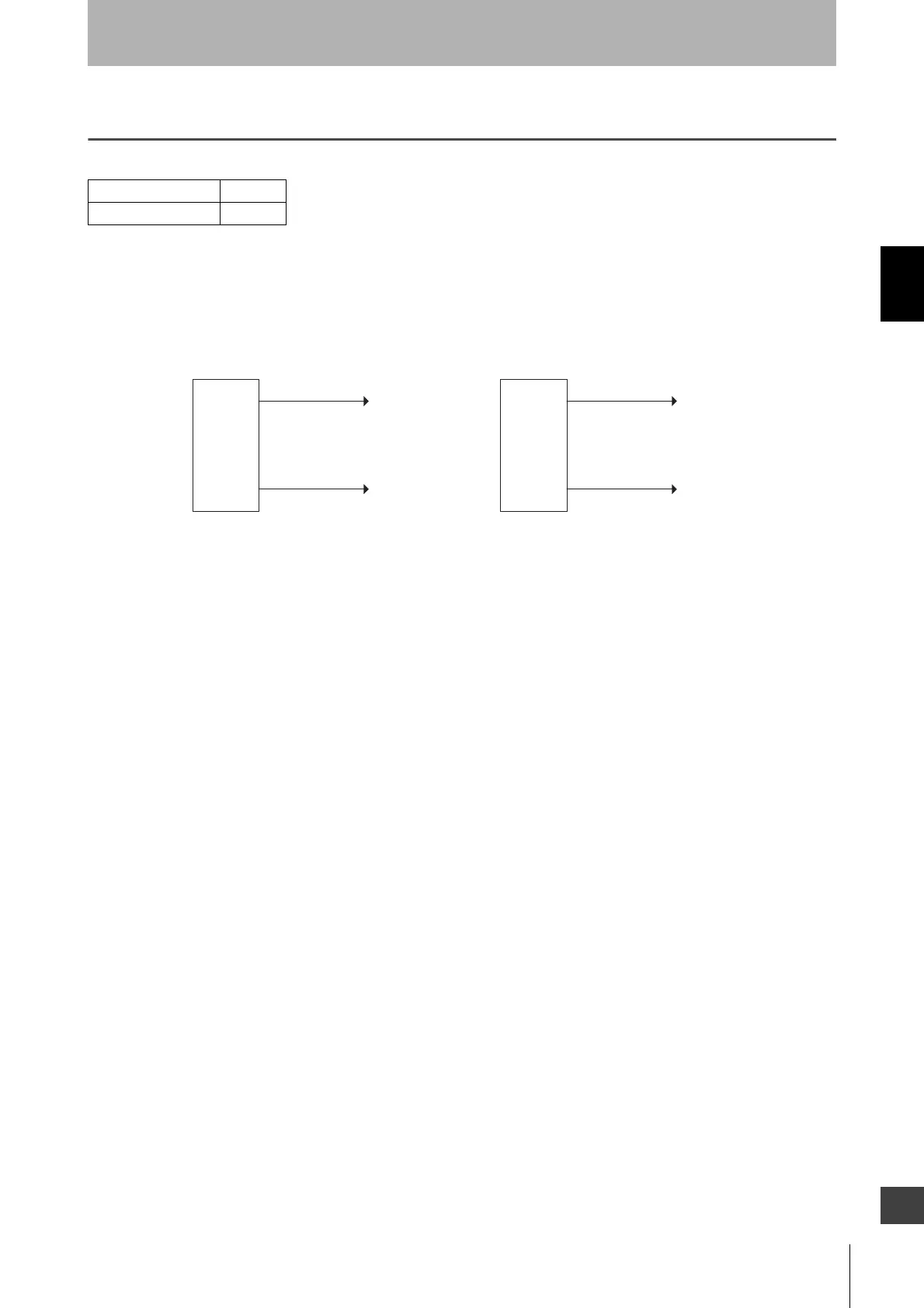
2-4-1. Overview
The F3SG-SR has the PNP/NPN Selection function for the user to select the polarity of the inputs and
outputs between PNP and NPN by changing the wiring. When the F3SG-SR system is set to PNP, the
PNP indicator is illuminated in green.
The F3SG-SR is set to PNP when the 24V/0V line (brown) is connected to +24 VDC and the 0V/24V
line (blue) to 0 V, The F3SG-SR is set to NPN when the 0V/24V line (blue) is connected to +24 VDC
and the 24V/0V line (brown) to 0 V.
When using an Intelligent Tap, wire the F39-JGA-D sensor connected with CN2 of the Intelligent Tap
in the same way as above.
2-4-2. Setting with Intelligent Tap
The user cannot make any changes to the settings of this function by the DIP Switch on the Intelligent
Tap.
2-4-3. Setting with SD Manager 3
The user cannot make any changes to the settings of this function by the SD Manager 3.
F3SG-SRA
F3SG-SRB
0V/24V (Blue)
+24 VDC
0V
PNP
0V
+24 VDC
NPN
F3SG-SR
emitter
and
receiver
F3SG-SR
emitter
and
receiver
24V/0V (Brown) 24V/0V (Brown)
0V/24V (Blue)

 Loading...


