44
Chapter2 Lockout Reset
F3SG-SR
User’s Manual
System Operation and Functions
2-7. Lockout Reset
When the cause of the LOCKOUT state is removed, you can release the LOCKOUT state of the
F3SG-SR by using either of the following methods.
• Cycle the power back ON
• Reset input
The resetting method by the reset input depends on the setting of PNP/NPN Selection as follows.
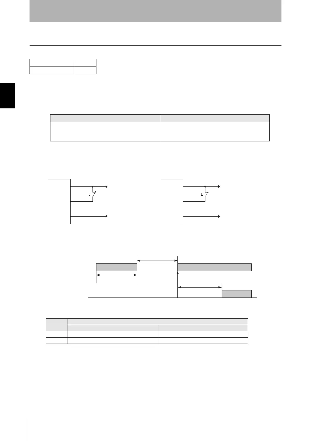
Basic wiring diagram
• External Device Monitoring not used and in Manual Reset mode
Timing chart
The table below shows the relation between the ON/OFF states and external lines.
F3SG-SRA
F3SG-SRB
PNP NPN
Open or apply 0 V to 1/2 Vs to the RESET line (yellow) for
1 s or longer, and then apply a voltage of Vs-3 V to Vs
again.
Open or apply 1/2 Vs to Vs to the RESET line (yellow) for
1 s or longer, and then apply a voltage of 0 to 3 V again.
Input
External connection
PNP NPN
ON Vs-3 V to Vs 0 to 3 V
OFF 0 V to 1/2 Vs, or open 1/2 Vs to Vs, or open
+24 VDC
0V
PNP
S1
0V
+24 VDC
NPN
S1
*Also used as Lockout Reset input line.
S1: Lockout or interlock reset switch
F3SG-
SR/PG
receiver
F3SG-
SR/PG
receiver
24V/0V (Brown)
RESET/EDM (Yellow) *
0V/24V (Blue)
24V/0V (Brown)
RESET/EDM (Yellow) *
0V/24V (Blue)
RESET
OFF
ON
OSSD
OFF
ON
Lockout reset
1 s or more
1 s or more
3s max.

 Loading...


