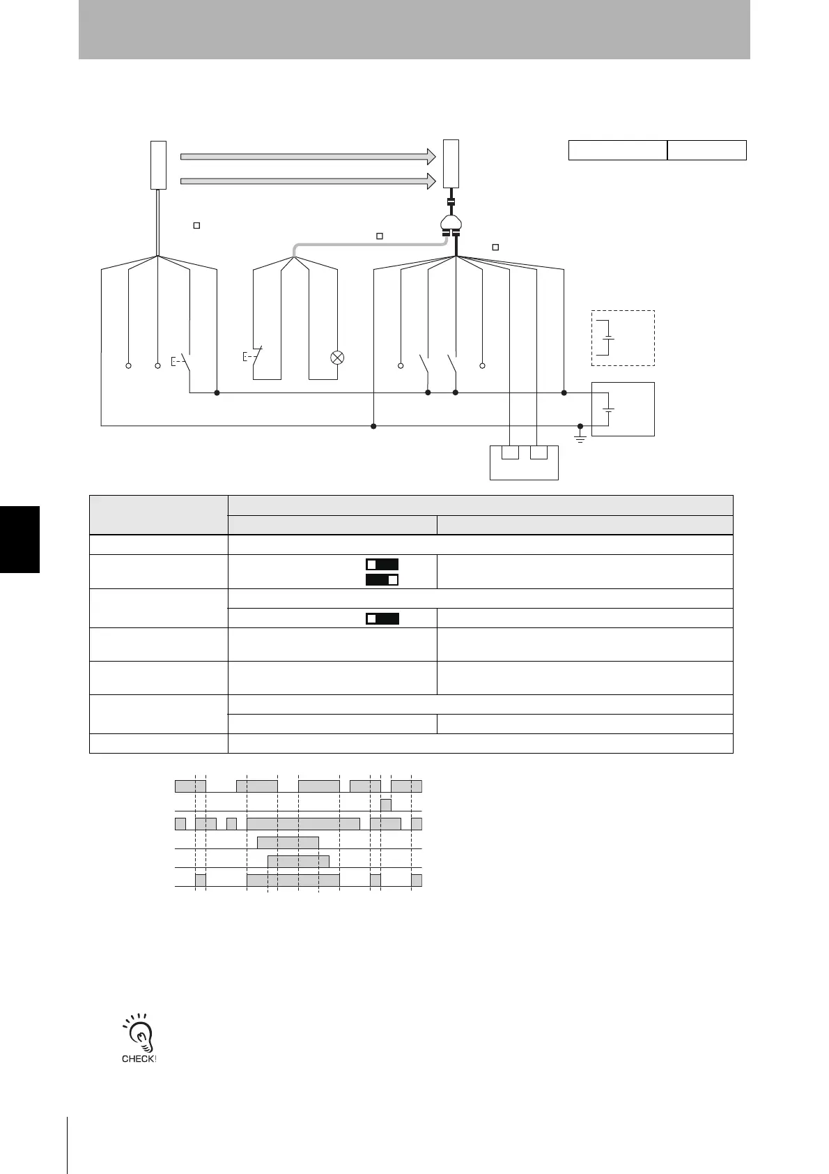
6-2-2-4. Standard Muting Mode/Exit-Only Muting Mode with Reset Switch Connector
S1: Test switch
S2: Lockout/interlock reset switch
S3: S4: Muting sensor
L1: Lamp
*1. Reverse the polarity of the power supply when using in the NPN
system. Select a safety controller of PNP or NPN type according to
the system of your application.
*2. Connect the line to 0 VDC if Operating Range Selection is used in
Short Mode.
*3. Refer to 6-3. Connectable Safety Control Units for more information.
*4.
The safety controller and the F3SG-SR must share the power supply
or be connected to the common terminal of the power supply.
*5. This is the case for a PELV circuit.
*6. Set the function with the DIP Switches on the Intelligent Tap or the
SD Manager 3, restore the settings to the F3SG-SR, and perform
wiring according to the wiring diagram.
*7. This is the example for the PNP system to stop emission when the
line is connected to 24 VDC and for the NPN to stop emission
when the line is connected to 0 VDC. If TEST switch is not
needed, refer to 2-6. External Test.
: Indicates a switch position
Function
Setting
DIPswitch SDManager3
EDM EDM Disabled (factory default setting)
Interlock *6 Manual Reset [Start interlock] : Enable
[Restart interlock] : Enable
Operating Range
Selection
Long : Open the OPERATING RANGE SELECT INPUT line of the emitter or connect the line to 24 VDC.
Long *6 [Operating Range Selection] : Long mode *6
Standard Muting Mode N/A [Muting] : Enable
[Muting mode] : Standard Muting (Installation Example 1/2) *6
Exit-Only Muting Mode *6 N/A [Muting] : Enable
[Muting mode] : Exit-Only Muting
External Test used Connect the TEST line of the emitter to 24V/0V via a test switch (NO contact). *7
N/A [External test signal inversion] : Disable
Optical Synchronization Open the COM(+) and COM(-) lines of the emitter.

 Loading...


