304
Chapter5 Wiring
F3SG-SR
User’s Manual
Wiring and Installation
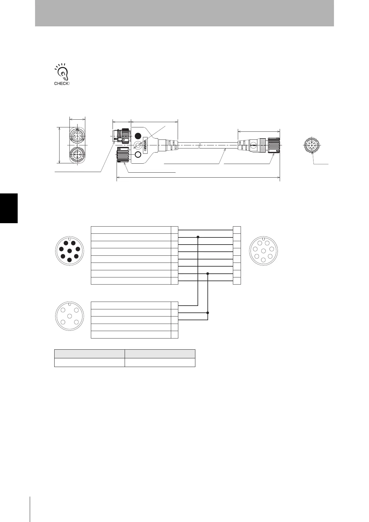
5-4-3-11. Reduced Wiring Connector System with Y-Joint Plug/Socket Connector
Reduced wiring can be achieved by using a Y-Joint Plug/Socket Connector (F39-GCNY2, sold separately).
When using the Y-Joint Plug/Socket Connector, the External Test, Operating Range Selection and Wired Synchronization
cannot be used.
Y-Joint Plug/Socket Connector (F39-GCNY2, sold separately)
<Internal wiring diagram>
Model Length
F39-GCNY2 0.5 m
17.7 45.5
40.7
15.0
M12 x 1
4.6 dia.
To control
panel side
To emitter
M12 IP67 connector, 8-wire
M12 IP67 connector, 5-wire
M12 IP67 connector, 8-wire
Insulated vinyl round cable, dia. 6
minimum bending radius R36
To receiver
Plug marked with ● (blue circle): Connect to control panel side
Socket marked with ○ (open circle): Connect to emitter
(Unit: mm)
Material: PBT (Main body)
1
2
3
4
5
6
7
8
Female
5
8
6
7
1
2
3
4
Male
5
8
4
3
2
1
7
6
Connected to Extended Socket-Straight Cable or
Extended Plug-Socket Cable of receiver
Connected to root cable or Extended
Plug-Socket Cable of emitter
Connected to root cable or Extended
Plug-Socket Cable of receiver
5
3
21
4
Female
1RESET/EDM
24V/0V
MUTE A/PRE-RESET/PSDI/COM(+)
MUTE B/COM(-)
OSSD 1
OSSD 2
0V/24V
AUX
2
3
4
5
6
7
8
124V/0V
TEST
0V/24V
COM(+)
OPERATING RANGE SELECT INPUT/COM(-)
2
3
4
5

 Loading...


