292
Chapter5 Wiring
F3SG-SR
User’s Manual
Wiring and Installation
5-4-3. Cable Connections
Extension of the cable must be within a specified length. If it isn't, safety functions may not
work properly, resulting in danger.
For the restrictions on the cable extension, refer to 1-5-1. F3SG-SR Series.
Perform wiring according to the following procedure.
1. Connect a gray Root-Straight Cable for Emitter (F39-JGC-L, sold separately) or Root-Plug Cable for
Extended for Emitter (F39-JGR3K-L, sold separately) to the emitter.
2. When extending the cable length, connect a gray Extended Plug-Socket Cable for Emitter and/or
Extended Socket-Straight Cable for Emitter (F39-JG-L, sold separately) to the emitter-side Root-
Plug Cable for Extended.
3. Connect a black Root-Straight Cable for Receiver (F39-JGC-D, sold separately) or Root-Plug Cable
for Extended for Receiver (F39-JGR3K-D, sold separately) to the receiver.
4. When extending the cable length, connect a black Extended Plug-Socket Cable for Receiver and/or
Extended Socket-Straight Cable for Receiver (F39-JG-D, sold separately) to the receiver-side
Root-Plug Cable for Extended.
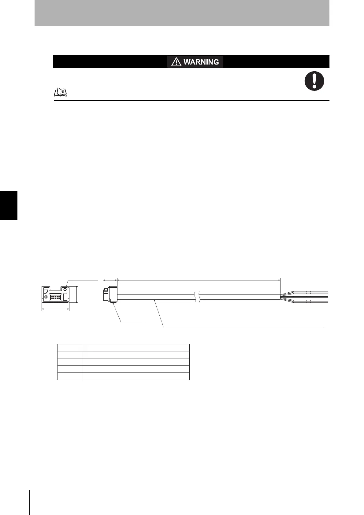
5-4-3-1. Root-Straight Cable
Root-Straight Cable for Emitter (F39-JGC-L, sold separately)
<Internal wiring diagram>
Connector
L
16.4
2-M2.5 screw
31.6
18.5
Oil-resistant PVC-insulated round cable, dia. 6
minimum bending radius R5, 5-wire
(Cross section of conductor: 0.3 mm
2
/insulator diameter: dia. 1.1 mm/AWG24)
(Unit: mm)
Brown
Black
Blue
White
Yellow
24V/0V
TEST
0V/24V
COM(+)
OPERATING RANGE SELECT INPUT/COM(-)

 Loading...


